Please update your browser. It looks like you are using an old version of the Microsoft Edge browser. To get the best experience with the Pfeiffer website, please update your browser.

1.3 Influences in real vacuum systems

1.3.1 Contamination

Vacuum chambers must be clean in order to reach the desired pressure as quickly as possible when they are pumped down. Typical contaminants of vacuum systems include

  • Residues from the production of the vacuum systems Oil and grease on surfaces, screws and seals
  • Application-related contaminants Process reaction products, dust and particles
  • Ambient-related contaminants Condensed vapors, particularly water that is adsorbed on the walls of the vessel.


Consequently, it is necessary to ensure that the components are as clean as possible when installing vacuum equipment. All components attached in the vacuum chamber must be clean and grease-free. All seals must also be installed dry. If the use of vacuum grease cannot be avoided, it must be used extremely sparingly, if at all, to aid installation but not as a sealant. If high or ultra-high vacuum is to be generated, clean lint-free and powder-free gloves must be worn during the assembly process.

1.3.2 Condensation and vaporization

All substances can occur in a liquid, solid or gaseous state. Their aggregate status is a function of pressure and temperature. Liquids are transformed into their gaseous state through vaporization, solids through sublimation. The separation of liquids or solids out of the gaseous phase is termed condensation. Since normal ambient air contains approximately 10 g of water vapor per m3, condensed water vapor is present on all surfaces.

1.3.3 Desorption, diffusion, permeation and leaks

In addition to water, other substances such as vacuum pump operating fluids can be adsorbed on surfaces. Substances can also diffuse out of the metal walls, which can be evidenced in the residual gas. In the case of particularly rigorous requirements, stainless steel vessels can be baked out under vacuum, thus driving the majority of the volatile components out of the metal walls.

Desorption

Gas molecules, (primarily water) are bound to the interior surfaces of the vacuum chamber through adsorption and absorption, and gradually desorb again under vacuum. The desorption rate of the metal and glass surfaces in the vacuum system produces a gas yield that declines over time as the coverage rate decreases. A good approximation can be obtained by assuming that after a given point in time 𝑑>𝑑0 the reduction will occur on a linear basis over time. 𝑑0 is typically assumed to be one hour. The gas yield can thus be described as:
𝑄des Desorption rate[Pa m3 s-1]
π‘ždes Desorption flow density (area-specific)[Pa m3 s-1 m-2]
𝐴 Area[m2]
𝑑 Time[s]

Diffusion with desorption

At operation below 10-6 hPa desorption of plastic surfaces, particularly the seals, assumes greater significance. Plastics mainly give off the gases that are dissolved in these plastics, which first must diffuse on the surface. Following extended pump downtimes, desorption from plastics can therefore dominate desorption from metal surfaces. Although the surface areas of the seals are relatively small; the decrease in the desorption rate over time occurs more slowly than in the case of metal surfaces. As an approximation it can be assumed that the reduction over time will occur at the square root of the time.

The gas produced from plastic surfaces can thus be described as:
  • 𝑄diff Diffusion rate[Pa m3 s-1]
  • π‘ždiff Diffusion flow density (area-specific)[Pa m3 s-1 m-2]
  • 𝐴𝑑 Surface of plastic material in the vessel[m2]
  • 𝑑 Time[s]
Similar effects also occur at even lower pressures in metals, where hydrogen and carbon escape in the form of CO and CO2, and can be seen in the residual gas spectrum. Formula 1-33 also applies in this regard.

Permeation and leaks

Seals, and even metal walls, can be penetrated by small gas molecules, such as helium,through diffusion. Since this process is not a function of time, it results in a sustained increase in the desired ultimate pressure. The permeation gas flow is proportional to the pressure gradient across the wall thickness and a material-dependent permeation constant.
  • 𝑄perm Diffusion rate[Pa m3 s-1]
  • π‘π‘Ž Pressure outside the vessel[Pa]
  • 𝑑 Wall thickness[m]
  • 𝐴 Surface of the vessel[m2]
  • π‘˜perm Permeation constant[m2 s-1 ]

Permeation first manifests itself at pressures below 10-8 hPa.
𝑄𝐿 describes the leak rate, i.e. a gas flow, which enters the vacuum system through leaks. The leakage rate is defined as the pressure rise over time in a given volume:
  • 𝑄𝐿 Leak rate[Pa m3 s-1]
  • Δ𝑝 Pressure change during measurement period[Pa]
  • 𝑉 Volume[m3]
  • Δ𝑑 Measurement period[s]


If a vessel is continuously pumped out at a volume flow rate 𝑆, an equilibrium pressure 𝑝eq will be produced if the throughput (Formula 1-16) is equal to the leakage rate 𝑄𝐿=𝑆⋅𝑝eq.

A system is considered to be adequately tight if the equilibrium pressure 𝑝eq is approximately 10 % of the working pressure. If, for example, a working pressure of 10-6 hPa is to be attained and the vacuum pump that is being used has a pumping speed of 100 l s-1, the leakage rate should not be more than s 10-6 Pa m3 s-1.

Leakage rates 𝑄𝐿 < 10-9 Pa m3 s-1 can usually be easily attained in clean stainless steel vessels.

The ultimate pressure achievable after a given period of time 𝑑 primarily depends upon all of the effects described above and upon the pumping speed of the vacuum pump. The prerequisite is naturally that the ultimate pressure will be high relative to the base pressure of the vacuum pump.
The various gas flows and the resulting pressures can be calculated for a given pumping time 𝑑 by using Formula 1-36 and by solving the equations in relation to the time. The achievable ultimate pressure is the sum of these pressures.

1.3.4 Bake-out

To achieve pressures in the ultra-high vacuum range (<10-8 hPa) the following conditions must be met:

  • The base pressure of the vacuum pump should be a factor of 10 lower than the required ultimate pressure.
  • The materials used for the vacuum chamber and components must be optimized for minimum outgassing and have an appropriate surface finish grade.
  • Metallic seals (e. g. CF flange connections or Helicoflex seals for ISO flange standards) should be used.
  • Clean work is a must for ultra-high vacuum, i. e. all parts must be thoroughly cleaned before installation and must be installed with grease-free gloves.
  • The equipment and high vacuum pump must be baked out.
  • Leaks must be avoided and eliminated prior to activating the heater. A helium leak detectors or a quadrupole mass spectrometer must be used for this purpose.


Bake-out significantly increases desorption and diffusion rates, and this produces significantly shorter pumping times. As one of the last steps in the manufacturing process, chambers for UHV use can be annealed at temperatures of up to 900 Β°C. Subsequent bake-out temperatures may reach up to 300 Β°C in tents. Pump manufacturers' instructions relating to maximum bake-out temperatures in the high vacuum pump flange normally restrict the maximum temperature during operation to 120 Β°C. If heat sources are used in the vacuum equipment (e. g. radiation heating), then the admissible radiated power must not be exceeded.

The equipment is put into operation after it has been installed. After reaching a pressure of 10-5 hPa the heater is switched on. During the heating process, all vacuum gauges must be operated and degassed at intervals of 10 hours. If stainless steel vessels with an appropriate surface finish grade and metal seals are used, bake-out temperatures of 120Β°C and heating times of approximately 48 hours are sufficient for advancing into the pressure range of 10-10 hPa.

Bake-out should be continued until 100 times the expected ultimate pressure is attained. The heaters for the pump and vacuum chamber are then switched off. After cool-down, the desired ultimate pressure will probably be achieved. At pressures of less than 5 Β· 10-10 hPa and large interior surface areas, it will be advantageous to use a gas-binding pump (titanium sublimation pump) that pumps the hydrogen escaping from the metals at a high volume flow rate.

1.3.5 Residual gas composition

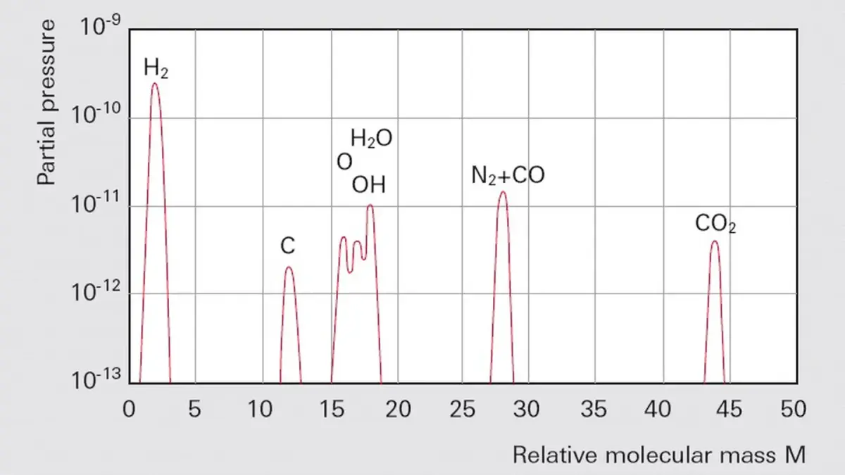
When working in ultra-high vacuum, it can be important to know the composition of the residual gas before starting vacuum processes or in order to monitor and control processes. The percentages of water (m/e = 18) and its fragment OH (m/e = 17) will be large in the case of vacuum chambers that are not clean or well baked. Leaks can be identified by the peaks of nitrogen (m/e = 28) and oxygen (m/e = 32) in the ratio N2/O2 of approx. 4 to 1.

Hydrogen (m/e = 2), water (m/e = 17 and 18), carbon monoxide (m/e = 28) and carbon dioxide (m/e = 44) will be found in well-baked chambers. No hydrocarbons will be found when using turbomolecular pumps. They are very effectively kept out of the chamber due to the high molecular masses and the resulting high compression ratios. A typical residual gas spectrum for a clean vessel evacuated by a turbomolecular pump is shown in Figure 1.10.
Further information on working with mass spectrometers is given in Chapter 6, Mass spectrometers and residual gas analysis.

1.3.6 Venting

To avoid undesired contamination, vacuum chambers should be vented with dry nitrogen instead of air. This prevents water vapor and other condensable contents of the ambient air (such as solvent vapors) from depositing (adsorbing) on the vessel walls. Every condensate would extend the subsequent evacuation due to the slow process of desorption compared to a pump-down operation. If a vessel had been vented with inert gas, it should only be opened to allow the necessary work to be carried out to the inside the vessel. Opening the vessel for long periods will result in water vapor from the ambient air entering due to convection caused by movement of maintenance personnel or due to diffusion.