Please update your browser. It looks like you are using an old version of the Microsoft Edge browser. To get the best experience with the Pfeiffer website, please update your browser.

3.5 Components and feedthroughs

A vacuum system has a number of single components that must be assembled to form a unit. With detachable, vacuum-sealed flange connections, components can be connected directly or through vacuum components, such as piping components or hoses. There are a number of standard components available, which are mainly made of stainless steel but also from aluminum. Vacuum junctions can be made from pipe components such as elbows, T- or cross-pieces, and adapters provide transitions from vacuum flanges to threads or VCR connections, and reducers or adapter pieces make it possible to change the nominal diameters or the flange systems.

If the mounting space is limited, the fewest possible flange connections should be installed; if the required adapter and connections cannot be realized with the standard components, custom components are used. These start with special-length full nipples and end with highly complex, individual special solutions.
3.5.1 Hoses and flexible connectors

The simplest form of an flexible connection is the plastic hose. Larger nominal diameters are enhanced by inlaid metal spirals, to prevent a constriction. Their ends are clamped to hose adapters and secured with hose clamps. Since plastic outgasses in the vacuum, such hoses should only be used for low and medium vacuum applications. For pressures better than 1 · 10-4 hPa, metal hoses are essential. They are cold-formed from thin-walled tubes in the form of concentric shafts and welded to the flange connections to seal them hermetically. Annealed corrugated hoses are stress relieved by annealing after deformation and thus have a lower restoring moment. However, deformation causes further cold working and depending on the degree of deformation, it omits the stress relief annealing again. Thin-walled corrugated hoses are very flexible and easy to deform.

Corrugated hoses shrink under vacuum. Therefore flexible connectors may act as hydraulic elements. Depending on the axial spring rate and the hydraulic cross-section of their profile, axial forces are created, which are transferred onto the flange connections. Large nominal diameters create enormous tensile forces, which must be considered when designing a system. While corrugated hoses are mainly used to connect two flanges in a space, spring bellows are used for axial compensation or absorption of vibrations. Their profile is very flexible, as it is compressed in the form of an omega-wave.

Membrane bellows are made from individual lamellas welded together. On a short installation length it is possible to achieve long, axial strokes and large bending angles. Due to the rigidity of the lamellas, a lateral offset is only possible through relatively many membrane pairs which form an S-shaped profile.

3.5.2 Viewports

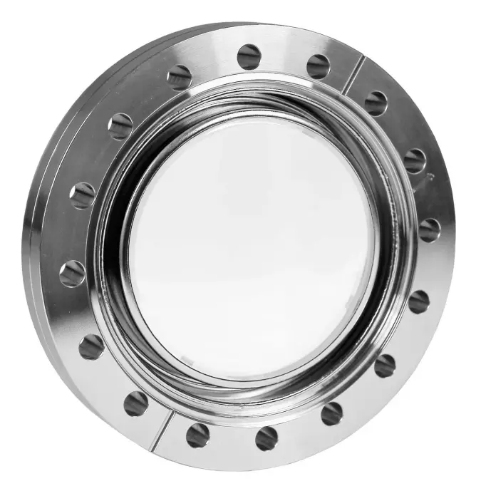
Sightglasses are primarily used to observe the interior of a vacuum chamber, including during the process. Therefore, borosilicate glasses of corresponding thickness are generally used and installed with elastomeric seals into a sight flange (ISO-KF, ISO-K and ISO-F viewports). For UHV applications and for high temperatures, the glasses are metalized and soldered (fused silica or sapphire glass) or fused (Kodial glass) with welding lips to compensate for the thermal expansion. They are welded and hermetically sealed to the weld lips of the sight flange. In order to minimize tension, CF viewports should only be fitted with annealed copper seals. In addition, the heating and cooling must be smooth and not too fast.

If viewports also serve the transfer of electromagnetic waves, their transmission range and optical quality must be considered. Glass holders with FKM gaskets for one-inch and two-inch sight glasses allow the installation of optical glasses in vacuum flanges. Viewports shutter prevent or reduce the pollution of viewports, for example during coating processes.

3.5.3 Electrical feedthroughs

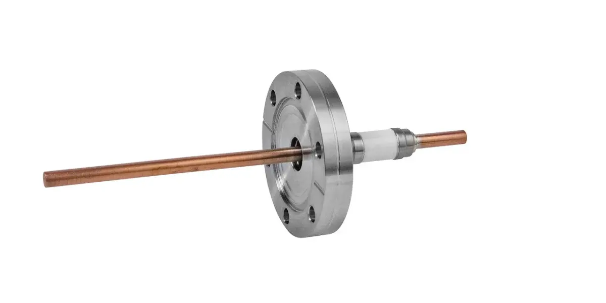
A major factor in engineering an electric feedthrough is the current capacity and voltage for which it will be used and the requirements it will have to satisfy with respect to vacuum-tightness and temperature resistance. Feedthroughs with organic insulating materials can only be used for lower voltages. Cast-resin feedthroughs are frequently used for moderate current loads and for moderate temperatures. With respect to their insulating resistance, feedthroughs with glass-to-metal fusings are suitable for high-voltage and weak-current feedthroughs for electronic devices.

Feedthroughs with ceramic insulation offer greater mechanical stability and temperature resistance than glass. In addition, ceramic (e.g. aluminum oxide) can also be produced in an insulating form that is suitable for high voltage. This is why ceramic feedthroughs are superior to glass feedthroughs for high voltages and high performance. Only rigid metal-to-ceramic connections should be considered for the most rigorous electrical, thermal and vacuum technology requirements.
It must be generally considered that higher temperatures reduce the electrical insulation effect and also decrease the ampacity of the conductor. Unless otherwise stated, the electrical data refer to room temperature. Moreover, the maximum operating voltages apply for one vacuum of less than 1 · 10-4 hPa. At higher pressures, small clearances between conductors with high voltage differences can lead to gas discharges and flashovers. In the vulnerable pressure range between 1 · 10-3 hPa, appropriate clearances must be provided between high-voltage conductors. Alternatively, potting with cast resin or shields made of glass or ceramic pipes can be useful in this regard.

Electrical feedthroughs are available as wire feedthroughs, as multiple feedthroughs with a plug or a feedthrough with coaxial connector. There are variations specifically for the transfer of high voltages or currents, or voltages of many signal voltages in a narrow installation space.

3.5.4 Other feedthroughs

Thermocouple feedthroughs transmit low thermoelectric voltages and must be tailored to the thermocouple used. The materials of the conductor pair for thermocouples must either be identical to those of the thermocouple or must be at least thermoelectrically comparable, so that a thermoelectric neutral transfer of thermoelectric voltage takes place. Elastomer sealed feedthroughs are also available for mineral insulated thermocouples and seal the sheath vacuum-tight through O-rings.

Feedthroughs for liquids
are flanges welded pipes with open ends or with Swagelok® or VCR fittings. Double-walled pipes are used for feedthroughs that carry cold or hot fluids, where the fluid-carrying pipes are thermally insulated from the flange.

Insulators
provide galvanic isolation to portions. The ceramics hermetically sealed and soldered to the flange connections can separate, depending on the length of the insulating distance, large potential differences in the high kV range.

Pipe feedthroughs
clamp with two in a row elastomer O-rings glass and metal pipes vacuum-tight.