-
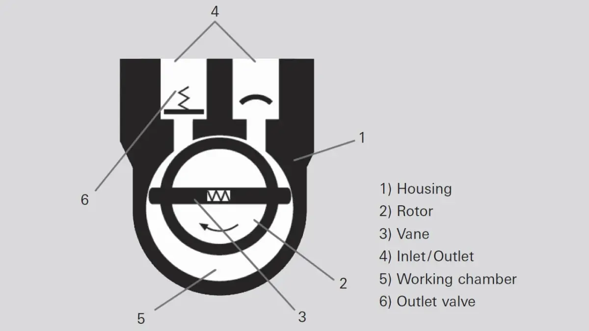
Figure 4.2: Operating principle of a rotary vane pump

In the case of gas ballast operation, a hole to the outside is opened, which empties into the sealed suction chamber on the front side. As a result, the pressure needed to open the outlet valve is attained at relatively low compression during the compression pumping phase. This allows a displaced gas/vapor mixture to be expelled before the vapor starts to condense. The final pressure reached during operation with gas ballast is higher than in operation without gas ballast.
Operating fluid, oil
Pump oil, which is also referred to as operating fluid, has multiple tasks to perform in a rotary vane pump. It lubricates all moving parts, fills both the dead volume under the outlet valve as well as the narrow gap between the inlet and outlet. It compresses the gap between the vanes and the working chamber and additionally ensures an optimal temperature balance through heat transfer.Multi-stage pumps
Rotary vane vacuum pumps are built in single- and two-stage versions. Two-stage pumps achieve lower ultimate pressures than single-stage pumps. Moreover, the effects of the gas ballast on the ultimate pressure are lower, as the ballast gas is only admitted at the high pressure stage.Vacuum safety valve
Depending upon the type of pump in question, rotary vane vacuum pumps may be equipped with a vacuum safety valve. The vacuum safety valve isolates the pump from the vacuum chamber in the event of intentional or unintentional standstill, and uses the displaced gas to vent the pumping system in order to prevent oil from rising into the vacuum chamber. After switching on the pump, it opens after a delay once the pressure in the pump has reached the approximate pressure in the vacuum chamber.4.2.2 Application
Rotary vane vacuum pumps can be employed universally throughout the entire low and medium vacuum ranges. Either a single- or double-stage pump can be used, depending upon the pressure range in question. Ideal operating conditions always exist if the medium to be pumped down will not condense at pump operating pressure and atmospheric pressure.Vapors
Vapors that can condense entirely or partially in the pump during the compression phase must also be displaced during distillation and drying processes. Opening the gas ballast valve helps in this case to displace the vapor through the pump without condensation. However the vapor compatibility is not always sufficient to prevent condensation. Condensates mix with the oil and cause the ultimate pressure to increase and diminish the lubricating capacity of the operating fluid. These factors can cause corrosion inside the pump. Before evacuating the vapors, the pump must be warmed up for at least half an hour with gas ballast. The higher temperature of the operating fluid reduces condensation. Additional measures to reduce condensation include obtaining the lowest possible outlet pressure and separate removal of condensates. A condensate separator at both the inlet and outlet sides should be used for this purpose. Back pressure at the outlet must be prevented with an oil mist filter and a vertical exhaust gas line. If an extraction system is available, the outlet should be connected to it.Dust, particles and chemicals
Within certain limits, filters and separators can protect the vacuum pump against wear and corrosion. Separators that are filled with polyester (SAS) or epoxy glass microfiber (DFT) filter inserts bind dust. Activated carbon filters (FAK) bind inorganic vapors, and their filter filling is replaceable. Inflowing hydrocarbons (oil vapor) can be catalytically incinerated in the heated catalytic trap (URB), and zeolite traps (ZFO or ST) adsorb various vapors. When saturated, they can be regenerated by baking them out. Condensates can be collected in the condensate separator (KAS or CT) and drained manually. Chemical oil filters (OFC) clean the pump oil with the aid of the oil pump that is integrated in the rotary vane pump.At high gas throughputs and when operated with gas ballast, oil mist is entrained out of the pump. An oil loss of 4 ml at a gas throughput of 100 kPa · m³ can be assumed. The oil vapor can be separated in an oil mist filter (ONF or OME) and returned to the pump’s oil circulation system through an additional return line (ORF or ODK).
However, if substances are also displaced that chemically attack the pump oil or that have such low vapor pressure that condensation in the pump cannot be avoided in spite of gas ballast and the above-mentioned accessories, a different type of backing pump should be selected.
4.2.3 Portfolio overview
Pfeiffer Vacuum rotary vane pumps are available as single- and two-stage versions. Their pumping speed and the attainable final pressure depend on the mains frequency.-
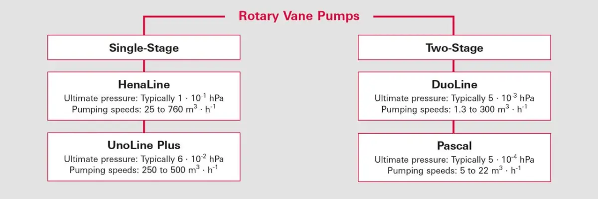
Figure 4.2: Pfeiffer Vacuum rotary vane pumps

4.2.3.1 Single-stage rotary vane vacuum pumps
HenaLine
HenaLine single-stage, oil-sealed rotary vane vacuum pumps generate a vacuum with pumping speeds of 25 to 1,920 m3 · h-1 with an ultimate pressure down to 0.3 hPa. They can be universally employed in many industrial and research environments. They can either be operated as a stand-alone pump or integrated into pumping stations. With appropriate accessories, these pumps are also suitable for use under the harshest operating conditions, i. e. at high inlet pressures as well as in cycle-mode operation. Oil mist filters, oil return systems and vacuum safety valves are all integrated as standard equipment. In addition to preventing pollution of the ambient air, they also protect the pump and the system. A gas ballast valve enables water vapor and other process vapors to be pumped down.
UnoLine Plus
UnoLine Plus pumps can be utilized employed for industrial applications. These rotary vane vacuum pumps have proven track records as both stand-alone and backing pumps for Pfeiffer Vacuum Roots pumps. An ultimate pressure of approximately 6 · 10-2 hPa can be attained. These pumps are water cooled and extremely insensitive to dust and dirt. They are equipped with an oil regeneration system. Condensates, contaminants and dust particles can be separated from the operating fluid, collected in the vapor separator and drained. The adjustable cooling water controller enables the UnoLine Plus pumps to maintain the required operating temperature. These pumps are equipped with gas ballast in order to pump down vapors.
HenaLine | |||
|---|---|---|---|
Model | Pumping speed | Ultimate pressure | Applications |
Hena 25 | 25 m³ · h-1 | 0.3 hPa | Electron beam welding, incandescent light bulb manufacturing, surface coating, vacuum drying, leak detection, metallurgy, gas recovery, load lock applications, simulation chambers |
Hena 40 | 40 m³ · h-1 | 0.3 hPa | |
Hena 60 | 63 m³ · h-1 | 0.3 hPa | |
Hena 100 | 100 m³ · h-1 | 0.3 hPa | |
Hena 200 | 200 m³ · h-1 | 0.3 hPa | |
Hena 250 | 250 m³ · h-1 | 0.3 hPa | |
Hena 300 | 300 m³ · h-1 | 0.3 hPa | |
Hena 400 | 400 m³ · h-1 | 0.3 hPa | |
Hena 630 | 630 m³ · h-1 | 0.3 hPa | |
Hena 1000 | 1,000 m³ · h-1 | 1.0 hPa | |
Hena 1600 | 1,920 m³ · h-1 | 0.7 hPa | |
Table 4.1: HenaLine performance data (all data refer to 50 Hz operation)
UnoLine Plus | |||
|---|---|---|---|
Model | Pumping speed | Ultimate pressure | Applications |
BA 251 | 250 m³ · h-1 | 5 · 10-2 hPa | Suitable for all industrial applications, e. g. metallurgy, transformer drying, coating, chemistry |
BA 501 | 500 m³ · h-1 | 6 · 10-2 hPa | |
Table 4.2: UnoLine Plus performance data (all data refer to 50 Hz operation)
4.2.3.2 Two-stage rotary vane vacuum pumps
Two-stage rotary vane pumps are suitable for applications in the low and medium vacuum ranges down to a pressure of 10-3 hPa. An integrated gas ballast feed allows condensable vapors to be pumped down.
DuoLine
DuoLine rotary vane vacuum pumps are powered by AC or DC motors, depending upon the size of the pump. In addition to the standard models, the following designs are also available: Magnetically coupled pumps (Duo M series) and corrosive gas pumps, both with and without magnetic coupling (Duo MC series).
Duo M series
M series pumps are equipped with a magnetic coupling with a hermetic sealing. This wear-free sealing concept hermetically seals the pumps, making them clean and environmentally friendly. The magnetic coupling minimizes maintenance resulting in significant savings.
PentaLine | |||
|---|---|---|---|
Model | Pumping speed | Ultimate pressure | Applications |
Penta 20 | 22 m³ · h-1 | 3 · 10-3 hPa | Ideally suited for turbopump pumping stations, analysis, industrial applications, research and development, coating |
Penta 35 | 34 m³ · h-1 | 3 · 10-3 hPa | |
Table 4.3: PentaLine performance data
DuoLine | |||
|---|---|---|---|
Model | Pumping speed | Ultimate pressure | Applications |
Duo 1,6 | 1.25 m³ · h-1 | 3 · 10-3 hPa | Turbopump pumping stations, analysis, research and development, coating |
Duo 3 | 2.5 m³ · h-1 | 3 · 10-3 hPa | |
Duo 6 | 5 m³ · h-1 | 3 · 10-3 hPa | |
Duo 11 | 9 m³ · h-1 | 3 · 10-3 hPa | |
Duo 35 | 32 m³ · h-1 | 3 · 10-3 hPa | |
Duo 65 | 62 m³ · h-1 | 2 · 10-3 hPa | |
Duo 125 | 115 m³ · h-1 | 2 · 10-3 hPa | |
Duo 255 | 250 m³ · h-1 | 3 · 10-3 hPa | |
Table 4.4: DuoLine performance data
Duo M series | |||
|---|---|---|---|
Model | Pumping speed | Ultimate pressure | Applications |
Duo 1,6 M | 1.25 m³ · h-1 | 3 · 10-3 hPa | Turbopump pumping stations, analysis, research & development, coating, non-explosive toxic gases |
Duo 3 M | 2.5 m³ · h-1 | 3 · 10-3 hPa | |
Duo 6 M | 5 m³ · h-1 | 3 · 10-3 hPa | |
Duo 11 M | 9 m³ · h-1 | 3 · 10-3 hPa | |
Duo 35 M | 32 m³ · h-1 | 3 · 10-3 hPa | |
Duo 65 M | 62 m³ · h-1 | 2 · 10-3 hPa | |
Duo 125 M | 115 m³ · h-1 | 2 · 10-3 hPa | |
Duo 255 M | 250 m³ · h-1 | 3 · 10-3 hPa | |
Table 4.5: Duo M series performance data
Duo MC series
The MC series pumps are suitable for corrosive gas applications. In contrast to standard pumps, they have a special gas ballast valve, through which inert gas can be admitted into the pump. In addition, the pumps are equipped with special vanes that are especially resistant to chemicals. All corrosive gas pumps in the MC series are ready for operation with chemical-resistant F4 or F5 (perfluoropolyether) operating fluids. The Duo MC pumps are especially suitable for pumping toxic gases because the hermetically sealed magnetic coupling prevents gas from escaping to the outside.
Pascal
Rotary vane vacuum pumps in the Pascal series in the pumping speed class of between 5 and 21 m3 · h-1 are built with either AC or DC motors. The inlet and outlet flange can be either vertical or horizontal for ideal integration or to enable accessories to be attached. Besides the standard range, the I series with forced lubrication and two different corrosive gas series are also available.
SD series
The SD series of rotary vane vacuum pumps is designed for noncorrosive gases. The natural lubrication (pumping speed class up to 21 m3 · h-1) minimizes the amount of oil discharge from the exhaust. The low pump temperature reduces the oil backflow at the final pressure to a minimum during long-term operation. As in all other pumps in the pumping speed class up to 21 m³ · h-1 the pump shaft seal is accessible without dismantling the pump block and field maintenance is easy as a result.
I series
Pumps in the I series are equipped with forced lubrication. This enhances their water vapor tolerance in comparison with the SD series. Forced lubrication allows I series pumps to achieve a very low noise level and low vibration.
C1 series
Forced lubrication pumps in the C1 series are particularly suitable for corrosive gas applications due to their FPM seals and chromium oxide coated shafts and the use of special materials for the housing, vanes, shaft sleeves and sightglasses. The two largest models in this series also have integrated oil filters and oil casing flushing device.
The C1 series is supplied with mineral oil.
Duo 20 MC series | |||
|---|---|---|---|
Model | Pumping speed | Ultimate pressure | Applications |
Duo 20 MC | 20 m³ · h-1 | 5 · 10-3 hPa | Corrosive gas applications, chemical labs, toxic non-explosive gases |
Duo 35 MC | 32 m³ · h-1 | 3 · 10-3 hPa | |
Duo 65 MC | 62 m³ · h-1 | 3 · 10-3 hPa | |
Table 4.6: Duo MC series performance data
Pascal SD series | |||
|---|---|---|---|
Model | Pumping speed 50 Hz | Ultimate pressure with Gas ballast | Applications |
2005 SD | 5 m³/h | 5 · 10-4 hPa | Industrial applications, analysis, research and development, leak detection |
2010 SD | 9 m³/h | 10.5 m³/h | |
2015 SD | 14 m³/h | 16.5 m³/h | |
2021 SD | 18 m³/h | 22 m³/h | |
Table 4.7: Pascal SD series performance data
Pascal I series | |||
|---|---|---|---|
Model | Pumping speed 50 Hz | Ultimate pressure | Applications |
2005 I | 5 m³/h | 6 m³/h | Analysis, research and development, drying, distillation |
2010 I | 9 m³/h | 10.5 m³/h | |
2015 I | 14 m³/h | 16.5 m³/h | |
2021 I | 18 m³/h | 22 m³/h | |
Table 4.8: Pascal I series performance data
C2 series
Pumps in the C2 series are also equipped with forced lubrication. The anticorrosive gas equipment of these pumps with bearing lubrication, a neutral gas flushing facility for degassing the operating fluid and the use of special vane materials is superior to the C1 series. The two largest models in this series are also fitted with connections for oil pressure sensors and oil temperature sensors. Armed with this anticorrosive gas equipment, Pascal C2 pumps are particularly suitable for use in etching and coating processes in semiconductor fabrication.The C2 series is supplied with perfluorinated operating fluids.
Pascal C1 series | |||
|---|---|---|---|
Model | Pumping speed | Ultimate pressure | Applications |
2005 C1 | 5 m³ · h-1 | 2 · 10-3 hPa | Corrosive gas application, chemical laboratories, load lock and transfer chamber chemical applications, sterilization |
2010 C1 | 10 m³ · h-1 | 2 · 10-3 hPa | |
2015 C1 | 15 m³ · h-1 | 2 · 10-3 hPa | |
2021 C1 | 21 m³ · h-1 | 2 · 10-3 hPa | |
2033 C1 | 30 m³ · h-1 | 3 · 10-3 hPa | |
2063 C1 | 60 m³ · h-1 | 3 · 10-3 hPa | |
Table 4.9: Pascal C1 series performance data
Pascal C2 series | |||
|---|---|---|---|
Model | Pumping speed | Ultimate pressure | Applications |
2010 C2 | 10 m³ · h-1 | 2 · 10-3 hPa | Coating, semiconductors (CVD, plasma etching, implantation), pumping pure oxygen |
2015 C2 | 15 m³ · h-1 | 2 · 10-3 hPa | |
2021 C2 | 21 m³ · h-1 | 2 · 10-3 hPa | |
2033 C2 | 30 m³ · h-1 | 3 · 10-3 hPa | |
2063 C2 | 60 m³ · h-1 | 3 · 10-3 hPa | |
Table 4.10: Pascal C2 series performance data
Oil types | Description | Achievable ultimate pressure | Applications | HenaLine, UnoLine Plus, DuoLine, PentaLine, OktaLine | Pascal |
P3 | Mineral oil for standard applications Extremely low vapor pressure | < 1 · 10-3 hPa | Air, noncorrosive gases, noble gases | ||
A120 | General purpose mineral oil without additives, all-purpose oil for 50 Hz | < 3 · 10-3 hPa | Air, noncorrosive gases, noble gases; high viscosity | ||
D1 | Diester oil for standard and special applications | < 5 · 10-2 hPa | Air, noncorrosive gases, noble gases, oxygen, mildly aggressive and organic solvents | ||
A155 | Synthetic oil on organic ester base | < 3 · 10-3 hPa | Hydrocarbon vapors, NH3, R134a, refrigerants; oxidation-resistant, resistant to polymerization (low slight deposit) | ||
F4 | Perfluoropolyether for special applications | < 1 · 10-3 hPa | Oxygen, ozone, halogens, organic and inorganic solvents, HCl, BF3, HF | for pumps < 20 m³ h-1 | |
F5 | for pumps > 20 m³ h-1 | ||||
A113 | Perfluoropolyether synthetic oil | < 5 · 10-3 hPa | Oxygen, ozone, halogens, organic and inorganic solvents, high resistance to corrosive gases, suitable for plasma etching | ||
A119 | General purpose mineral oil without additives, all-purpose oil for 60 Hz | < 3 · 10-3 hPa | Air, noncorrosive gases, noble gases; low viscosity, therefore good start-up properties at low temperatures | ||
A121 | Double-distilled mineral synthetic oil with antioxidant additive | < 3 · 10-3 hPa | Cyclic pumping at atmospheric pressure, for high temperatures and pressures, resistant to acidic and organic vapors; not suitable for plasma etching | ||
A102 | Mineral oil with anti-emulsifier | < 3 · 10-2 hPa | Oil and water separation (anti-emulsion), water vapor drying and pumping, freeze-drying | ||
A111 | Additivated hydro-carbon anti-emulsion mineral oil | < 1 · 10-2 hPa | Gas circulation and gas return; oxidation-sensitive (not suitable for frequent cycles at atmospheric pressure) | ||
A200 | Temperature-stable, mineral synthetic oil | < 2 · 10-3 hPa | Resistant to corrosive gases and ionizing plasma; low slight backflow | ||
A300 | Double-distilled white mineral oil without additives | < 5 · 10-3 hPa | High resistance to corrosive gases and ionizing plasma; resistant to halogens and Lewis acids; low slight backflow |
Table 4.11: Oil types for Backing pumps and Roots pumps
4.2.3.3 Operating fluid selection
Since operating fluid comes into contact with the media to be pumped, it is exposed to the influences of the media in question. Consequently, operating fluid should be selected on an individual basis in accordance with the respective application. Pfeiffer Vacuum offers various types of operating fluids that are suitable for all major applications. The pumps are factory-set for one type of operating fluid. The ultimate pressures of the rotary vane vacuum pumps that are specified in the catalog can only be ensured when using the operating fluid recommended by Pfeiffer Vacuum. The manufacturer cannot accept any liability for damage attributable to the use of other operating fluids. Different types of oil should never be mixed. Some oils do not mix and can cause damage to the pumping system.
4.2.3.4 Accessories
Dust separators (SAS or DFT)
If the process produces dust, a dust separator must be installed upstream of the pump since particles result in increased wear and clog up the lubrication circuit. There are various types available to fit the connection flange on the pump.
Condensate separator (KAS or CT)
Condensates can form in the inlet and outlet lines of vacuum systems when pumping down vapors and these can result in corrosion as well as adversely affect the properties of the lubricant. To protect the pump against these condensates, we recommend providing a condensate separator in both the inlet and outlet lines.
Oil mist separator (ONF or OME)
Oil mist separators, also known as oil mist filters, are fitted to the outlet port of rotary vane pumps. They prevent the air from being contaminated by the oil mist that the pump discharges in greater or lesser quantities, depending upon the operating pressure. The separator consists of a cylindrical filter element and a plastic or aluminum housing with an oil collection chamber.
Oil return system (ORF or ODK)
The purpose of oil return systems is to collect and return the atomized pump oil. They are used for all applications involving a high discharge of operating fluid from the rotary vane pump, particularly in high pressure applications or frequent cyclical operation. The use of an oil return system lowers the operating costs and increases process stability, especially where special oils are used in fluorine and nuclear technology. The oil used in the oil mist separator is collected in a volume and returned to the vacuum pump.
Zeolite trap (ZFO or ST)
A zeolite trap uses adsorption to prevent the backflow of hydrocarbons from rotary vane vacuum pumps to vacuum components or vessels on the inlet side. The adsorption agent can be regenerated by baking it out. The regeneration intervals will depend upon the process concerned.
Catalytic trap (URB)
A catalytic trap prevents the backflow of hydrocarbons from single- or two-stage rotary vane vacuum pumps. This is accomplished through catalytic incineration of hydrocarbons at an operating temperature of 250°C to form CO2 and water vapor. The oxygen that is admitted into the process chamber through periodic venting suffices for self-regeneration. This means that the regeneration intervals are independent of the process in question. Water cooling is required for direct installation of the traps on the inlet ports and/or for use on single-stage rotary vane pumps.
Activated carbon filters (FAK)
Activated carbon filters are used if a wide range of chemicals are present. These include hydrogen sulfide, cyanide, mercury, ammonia, sulfur oxide, nitrous gases, as well as vaporous solvents, acids and alkaline solutions. The activated carbon filters are supplied with a first filling. This filling is replaceable. The service life of the filling is dependent upon the process involved.
Mechanichal and chemical oil filter (OFM, OFC or DE)
The chemical oil filter is interposed in the oil circulation systems of rotary vane pumps. This oil filter strains off dust or particulate matter reaching the operating fluid from the process. In addition, the chemical oil filter adsorbs corrosive substances from the oil. This reduces pump wear and enhances the service life.
Nitrogen cold trap (KLF or LNT)
Nitrogen cold traps are inserted between the vacuum system and the rotary vane pump. They freeze out condensable media from the process gas flow. Rotary vane pumps can be effectively protected from chemical or solvent attack in this way. These traps are available in a standard aluminum version or in a corrosion-resistant stainless steel version. Coolant use and service life depend on the particular application. When evacuating cryogenic vessels, a cold trap can also protect the vacuum chamber from backflowing operating fluid vapors from the rotary vane pump.
Automatic gas ballast valve (AGB)
The automatic gas ballast valve is the electrical, remote-controlled version of the manual gas ballast. It consists of an electromagnetic valve (closed when currentless) which allows gas to be fed into the high pressure stage of the pump. The automatic gas ballast can be connected to a neutral gas source. The automatic valve should be used if used frequently or if there is restricted access to the pump.
Oil level monitoring (OLS)
An oil level monitoring device is fitted directly to the rotary vane pump between the oil tank and the sightglass. If a large number of pumps need to be monitored or if the pump is installed in an operating environment which is difficult to access, the oil level monitoring system allows the pump to be conveniently monitored. For selected types of pumps, operations monitoring units are available which monitor either one or more operating parameters of the rotary vane pump. This includes the oil pressure, oil level, the temperature of the operating fluid and the outlet temperature.
-
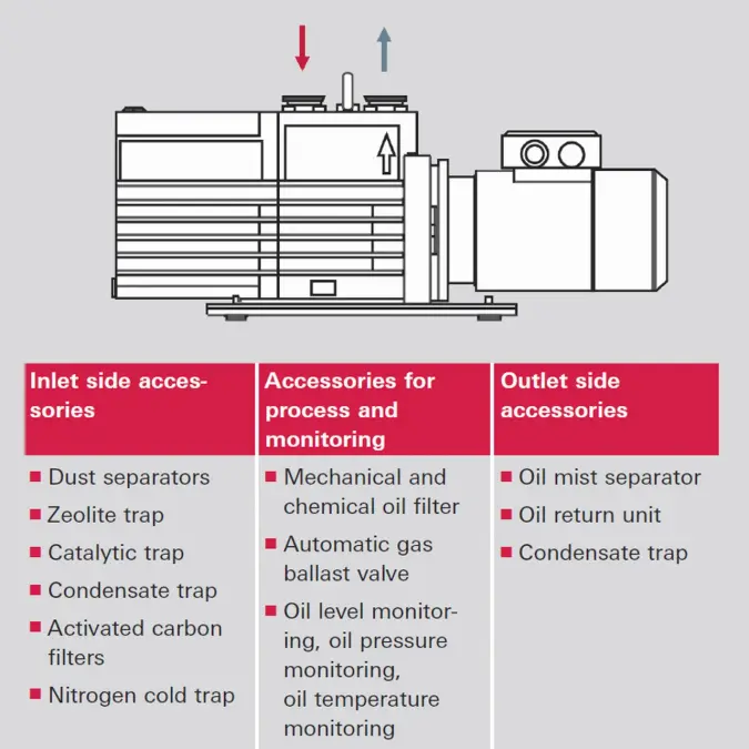
Figure 4.4: Accessories for rotary vane pumps
