Please update your browser. It looks like you are using an old version of the Microsoft Edge browser. To get the best experience with the Pfeiffer website, please update your browser.

Contact Customer portal
Global
  • EN
  • DE
  • ZH
  • KO

2.2 Calculations

2.2.1 Dimensioning a Roots pumping station

Various preliminary considerations are first required in dimensioning a Roots pumping station.

Compression ratio


The compression ratio K_0 ​ of a Roots pump is typically between 5 and 70. To determine this ratio, we first consider the volume of gas pumped and the backflow by means of conductivity C_{R} ​, as well as the return flow of gas from the discharge chamber at pumping speed S_R​:
  • S Volume flow rate (pumping speed)
  • S0 Theoretical pumping speed on the intake side
  • SR Pumping speed of return gas flow
  • CR Conductivity
  • pa Inlet pressure
  • pv Backing vacuum pressure

Selecting S as being equal to 0 we obtain the compression ratio
K0 Compression ratio

In the case of laminar flow the conductance is significantly greater than the pumping speed of the backflow. This simplifies Formula 2-2 to
In the molecular flow range, the pumping speed is still greatest on the intake side, but the pumping speed of the backflow is now considerably greater than the conductance. The compression ratio is therefore:
At laminar flow (high pressure), the compression ratio is limited by backflow through the gap between the roots lobes and the housing. Since conductance is proportional to mean pressure, the compression ratio will decrease as pressure rises.
In the molecular flow range, the return gas flow SR⋅pv from the discharge side predominates and limits the compression ratio toward low pressure. Because of this effect, the use of Roots pumps is restricted to pressures pa of more than 10-4 hPa.

Pumping speed

Roots pumps are equipped with overflow valves that allow maximum pressure differentials Δpd of between 30 and 60 hPa at the pumps. If a Roots pump is combined with a backing pump, a distinction must be made between pressure ranges with the overflow valve open (S1) and closed (S2). Since gas throughput is the same in both pumps (Roots pump and backing pump), the following applies:
  • S1 Pumping speed with overflow valve open
  • SV Pumping speed of backing pump
  • pv Fore-vacuum pressure
  • Δpd maximum pressure differential between the pressure and intake side of the Roots pump

As long as the pressure differential is significantly smaller than the fore-vacuum pressure, the pumping speed of the pumping station will be only slightly higher than that of the backing pump. As backing vacuum pressure nears pressure differential, the overflow valve will close and will apply
Let us now consider the special case of a Roots pump working against constant pressure (e. g. condenser mode). Formula 2-3 will apply in the high pressure range. Using the value CR in Formula 1 and disregarding the backflow SR against the conductance value CR we obtain:
At low pressures, SR from Formula 2-4 is used and we obtain
From Formula 2-6 , it can be seen that S tends toward S0 if the compression ratio K0 is significantly greater than the ratio between the theoretical pumping speed of the Roots pump S0 and the fore-vacuum pumping speed SV.
Selecting the compression ratio, for example, as equal to 40 and the pumping speed of the Roots pump as 10 times greater than that of the backing pump, then we obtain S = 0.816 ⋅S0
For the purposes of adjustment for use in a pumping station the theoretical pumping speed of the Roots pump should therefore not be more than ten times greater than the pumping speed of the backing pump.
Since the overflow valves are set to pressure differentials of around 50 hPa, virtually only the volume flow rate of the backing pump is effective for pressures of over 50 hPa. If large vessels are to be evacuated to 100 hPa within a given period of time, for example, an appropriately large backing pump must be selected.
Let us consider the example of a pumping station that should evacuate a vessel with a volume of 2 m³ to a pressure of 5 · 10-3 hPa in 10 minutes. To do this, we would select a backing pump that can evacuate the vessel to 50 hPa in 5 minutes. The following applies at a constant volume flow rate:
  • t1 Pump-down time of backing pump
  • V Volume of vessel
  • S Pumping speed of backing pump
  • p0 Initial pressurep1Final pressure

By rearranging Formula 2-9, we can calculate the required pumping speed:
Using the numerical values given above we obtain:
We select a Hepta 100 with a pumping speed 𝑆𝑉 = 100 m³ h-1 as the backing pump. Using the same formula, we estimate that the pumping speed of the Roots pump will be 61 l s-1 = 220 m³ h-1, and select an Okta 500 with a pumping speed 𝑆0 = 490 m³ h-1 and an overflow valve pressure differential of Δ𝑝𝑑 = 53 hPa for the medium vacuum range.
From the table below, we select the fore-vacuum pressures given in the column 𝑝𝑣, use the corresponding pumping speeds 𝑆𝑉 for the Hepta 100 from its pumping speed curve and calculate the throughput: 𝑄=𝑆𝑉⋅𝑝𝑣.
The compression ratio
is calculated for an open overflow valve up to a fore- vacuum pressure of 56 hPa. K0 for fore-vacuum pressures ≤ 153 hPa is taken from Figure 2.1. There are two ways to calculate the pumping speed of the Roots pump:
S
1 can be obtained from Formula 2-5 for an open overflow valve, or S2 on the basis of Formula 2-6 for a closed overflow valve.

As the fore-vacuum pressure nears pressure differential Δpd,S1 will be greater than S2. The lesser of the two pumping speeds will always be the correct one, which we will designate as S. The inlet pressure is obtained with the formula:

Pump-down times

The pump-down time for the vessel is calculated in individual steps. In areas with a strong change in pumping speed, the fore-vacuum pressure intervals must be configured close together. Formula 2-9 is used to determine the pump-down time during an interval, with S being used as the mean value of the two pumping speeds for the calculated pressure interval. The total pump-down time will be the sum of all times in the last column of Table 2-1.
The pump-down time will additionally be influenced by the leakage rate of the vacuum system, the conductances of the piping and of vaporizing liquids that are present in the vacuum chamber, as well as by degassing of porous materials and contaminated walls. Some of these factors will be discussed in Sections 2.2.3.1 and 2.3. If any of the above-mentioned influences are unknown, it will be necessary to provide appropriate reserves in the pumping station.

2.2.2 Condenser mode

In many vacuum processes (drying, distillation), large volumes of vapor are released that have to be pumped down. Moreover, significant volumes of leakage air will penetrate into large vessels, and those substances that are being vaporized or dried will release additional air that is contained in pores or dissolved in liquids.
In drying processes, the vapor can always be displaced against atmospheric pressure by a vacuum pump having sufficient water vapor capacity and can then be condensed there. However, this process has the following disadvantages:
  • The pump must be very large
  • A large volume of gas ballast air will be entrained which, together with the vapor, will carry a great deal of oil mist out of the pump
  • It will be necessary to dispose of the resulting condensate from the water vapor and oil mist, which is a costly process

Distillation processes operate with condensers, and the object is to lose as little of the condensing distillate as possible through the connected vacuum pump.
Let us consider a vacuum chamber containing material to be dried, to which enough energy will supplied by heat that 10 kg of water will evaporate per hour.
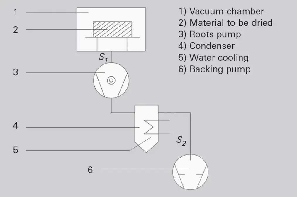
In addition, 0.5 kg of air will be released per hour. The pressure in the chamber should be less than 10 hPa. A pumping station in accordance with Figure 2.3 is used for drying, enabling the steam to be condensed cost-effectively through the use of a condenser.
The material to be dried (2) is heated in the vacuum chamber (1). The Roots pump (3) pumps the vapor / air mixture into the condenser (4), where a major portion of the vapor condenses.
The condenser is cooled with water. The condensing water at a temperature of 25°C is in equilibrium with the water vapor pressure of 30 hPa. An additional vacuum pump (5) pumps the air content, along with a small volume of water vapor, and expels the mixture against atmospheric pressure. The first step is to calculate the gas flow from the chamber: 𝑄=𝑝𝑣𝑐⋅𝑆1
With the ideal gas law according to Formula 1-15 we obtain

we obtain a gas throughput for air of 12 Pa m3 s-1 and for water vapor of 385 Pa m3s-1, together 397 Pa m3s-1. Divided by the inlet pressure 𝑝𝑣𝑐 von 1000 Pa we obtain a pumping speed 𝑆1 von 0.397 m3s-1 or 1429 m3h-1.
When evacuating the condenser, the partial air pressure should not exceed 30 %, i. e. a maximum of 12.85 hPa. It follows from this that:
With a gas throughput for air of 12 Pa m3 s-1 and a pressure of 1285 Pa, a pumping speed S2 of 0.031 m3 s-1 or 112 m3 h-1 is obtained.

We therefore select a Hepta 100 screw pump as the backing pump. Because its pumping speed is somewhat lower than the calculated one, this pump will achieve a slightly higher partial air pressure. And we select an Okta 2000 with the following values as the Roots pump:

S
0 2065 m³ h-1
Δpd 35 hPa differential pressure at the overflow valve
K0 28 where pv= 43 hPa

We estimate the inlet pressure pa = 1000 Pa and calculate S1 in accordance with Formula 2-7.
We obtain a pumping speed S1 of 0.506 m3 s-1 or 1.822 m3 h-1.

With
and a value for pa vof 785 Pa we obtain the inlet pressure in the drying chamber, and by using this figure again in Formula 2-7 we arrive at the more precise pumping speed S1 = 1.736 m³ h-1 for an inlet pressure pa = 823 Pa.
We calculate the condenser for a 10 kg h-1 volume of vapor to be condensed. The following applies for the condensation surface area:
Where:
  • 𝑄𝑤𝑎𝑡𝑒𝑟2.257 ⋅ 106 Ws kg-1
  • 𝑚𝑤𝑎𝑡𝑒𝑟10 kg
  • 𝑡 3600 s
  • Δ𝑇𝑚 60 K
  • 𝑘 400 W m-2 K-1

we obtain a condensation surface area of 𝐴𝑘 0.261 m2.
The vapor is heated by more than 100 K through the virtually adiabatic compression, however it re-cools on the way to the condenser. So the assumption that Δ𝑇𝑚 = 60 K is quite conservative. The thermal transmission coefficient 𝑘 [20] decreases significantly as the concentration of inert gas increases, which results in a larger condensation surface area. Inversely, with a lower concentration of inert gas, it is possible to work with a larger backing pump and a smaller condensation surface area. Particular attention should be paid to small leakage rates, as they, too, increase the concentration of inert gas.
Further technical details can be obtained from the special literature [21].
In the interest of completeness, let us again consider the entire sequence of the drying process: a pressure equilibrium initially occurs in the drying chamber, which results from the water volume that is being vaporized and that is caused by the heating-up of the material to be dried and the volume flow rate of the Roots pump.
The Roots pump advances the water vapor into the condenser, where it condenses. Because laminar flow prevails there, the vapor flow advances the inert gas released by the material to be dried into the condenser.
Were the backing pump to be shut down, the entire condensation process would quickly come to a stop, as the vapor could only reach the condensation surface area through diffusion. As the drying process progresses, the volume of vapor decreases and less condenses in the condenser; however the concentration of vapor extracted by the backing pump will tend to be larger if the concentration of inert gas decreases. If the vapor pressure in the condenser drops below the condensation threshold, the condensate will begin to re-evaporate. This can be prevented if the condensate drains into a condensate storage vessel via a valve and this valve closes when the vapor pressure falls below the condensation pressure.
In the case of large distillation systems, the pumping speed of the backing pump should be regulated on the basis of the condensation rate. This can be accomplished, for example, with the aid of a dosing pump that uniformly discharges the volume of pumped condensate from the storage vessel. When the concentrate level in the storage vessel falls below a given level, the backing pump’s inlet valve opens and the inert gas that has collected in the condenser is pumped down. The condensation rate now increases again, the condensate level increases and the backing pump’s inlet valve closes again. This arrangement means that the system pumps only when the condensation rate is too low, and only little condensate is lost.

Summary

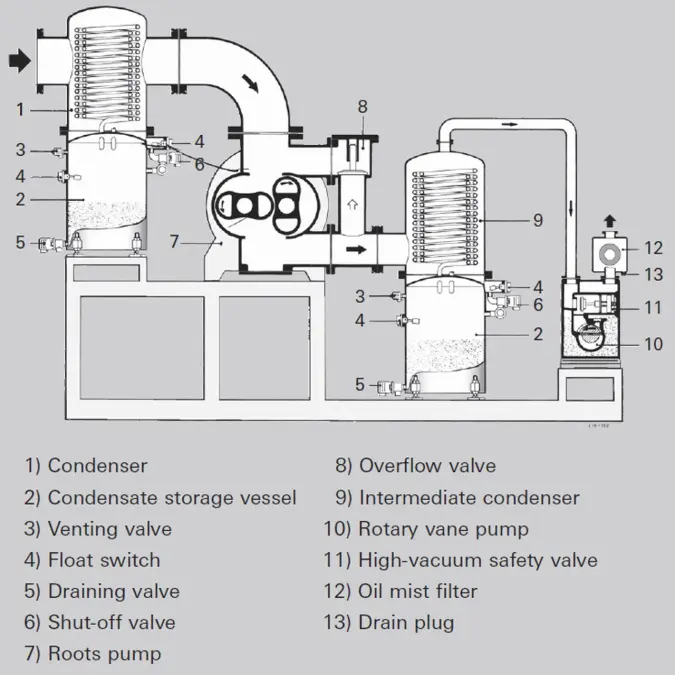
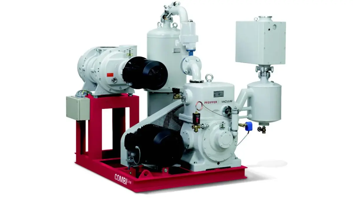
When pumping down vapors (drying, distillation), the major pumping effect can be provided by a condenser. Depending upon pressure and temperature conditions, either one or two condensers can be used (Figure 2.4). The condenser between the Roots pump and backing pump is more effective, as the vapor flows into the condenser at a higher temperature and higher pressure, and a small backing pump evacuates only a portion of the vapor. In distillation, condensate loss can be minimized by regulating the pumping speed of the backing pump.
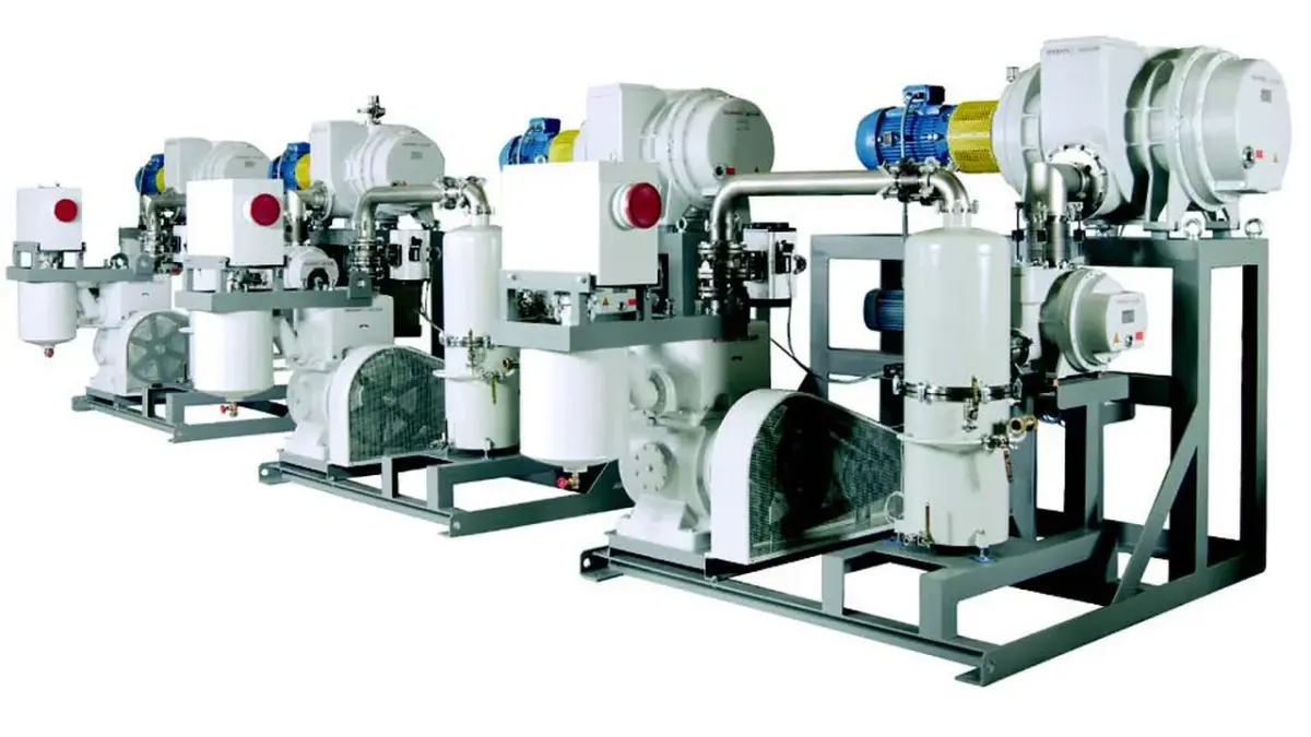
The above-mentioned theoretical principles are frequently used to configure Roots pumping stations. Figure 2.5 shows a vacuum solution for reducing the residual moisture of the paper material used in the production of submarine cables. A pre-condenser (not shown) condenses the water vapor mainly during the first drying phase at high process pressures. An intermediate condenser protects the downstream BA 501 rotary vane pump and condenses the water vapor mainly during a second drying phase.
Figure 2.6 shows a Roots pumping station used for transformer drying The intermediate condenser reduces the residual moisture of the material used to the extent that the water vapor capacity of the downstream BA 501 rotary vane pump is not exceeded.

2.2.3 Turbopumping stations

2.2.3.1 Evacuating a vessel to 10-8 hPa with a turbopumping station

A vessel made of bright stainless steel is to be evacuated to a pressure 𝑝𝑏 of 10-8 hPa in 12 hours. As can be seen from Chapter 1.3, there are other effects to consider in addition to the pure pump-down time for air. Both desorption of water vapor and adsorbed gases as well as outgassing from seals will lengthen the pump-down time. The pump-down times required to attain the desired pressure of 10-8 hPa are comprised of the following:
  • 𝑡1 =Pump-down time of the backing pump to 0.1 hPa
  • 𝑡2 = Pump-down time of the turbopump to 10-4 hPa
  • 𝑡3 = Pumping time for desorption of the stainless steel surface
  • 𝑡4 = Pumping time for outgassing the FPM seals
The desired base pressure 𝑝𝑏 sis comprised of the equilibrium pressure caused by gas flowing into the vessel through leaks and permeation 𝑄𝑙 , as well as by gases released from the metal surface 𝑄𝑑𝑒𝑠,𝑀 and the seals 𝑄𝑑𝑒𝑠,𝐾:
The backing pump should evacuate the vessel to 0.1 hPa in 𝑡1 of 180 s, and should also be able to achieve this pressure with the gas ballast valve open. The volume flow rate can be obtained in accordance with Formula 2-9:
We select a Duo 35 with a pumping speed of Sv = 35 m3 h-1.
The turbomolecular pump should have approximately 10 to 100 times the pumping speed of the backing pump in order to pump down the adsorbed vapors and gases from the metal surface. We select a HiPace 700 with a pumping speed SHV of 685 l s-1. Using Formula 2-9 we obtain

Desorption from the surface of the vessel

Gas molecules (primarily water) adsorb on the interior surfaces of the pressure chamber and gradually vaporize again under vacuum. The desorption rates of metal surfaces decline at a rate of 𝑡−1 ab. Time constant 𝑡0 is approximately 1 h.

Using Formula 1-32 from Chapter 1
we calculate the time taken to attain the base pressure
The resulting time of 741 hours is too long. The process must be shortened by baking out the vessel. The bakeout temperature is selected so as to prevent harming the most temperature-sensitive of the materials used. In our example, the temperature is restricted by the use of FPM seals which can easily withstand a temperature of 370 K. The desorption speed will be increased theoretically by more than a factor of 1,000 as a result [22]. And the bake-out time will in effect be shortened to several hours.

High desorption rates can also be lowered by annealing the vessel under vacuum or by means of certain surface treatments (polishing, pickling).

Since many pre-treatment influences play a role, precise prediction of the pressure curve over time is not possible. However in the case of bake out temperatures of around 150°C, it will suffice to turn off the heater after attaining a pressure that is higher by a factor of 100 than the desired base pressure. The desired pressure pb3 ill then be attained after the vacuum chamber has cooled down.

Seal desorption

The outgassing rates of plastic are important if operation is at temperatures of below 10-6 hPa. Although the surface areas of the seals are relatively small, desorption decreases only according to the factor
given in Formula 1-33 in Chapter 1.
The reason for this is that the escaping gases are not only bound on the surface, but must also diffuse out of the interior of the seal. With extended pumping times, desorption from plastics can therefore dominate desorption from the metal surfaces. The outgassing rate of plastic surfaces is calculated according to Formula 1-33 in Chapter 1.
We use Qdes,K=S⋅pdes,K and obtain the following for
In this connection t0 = 3600 s and the associated value qdes,K is read from the chart [23] for FPM. It can be seen that the contribution to pump-down time made by desorption of the cold-state seal is of a similar order of magnitude as that of the metal surface.

Since the diffusion of the gases released in the interior of the seal will determine the behavior of the desorption gas flow over time, the dependence of diffusion coefficient D upon temperature will have a crucial influence on pumping time:
As temperature rises, the diffusion coefficient increases as well; however it will not rise as sharply as the desorption rate of the metal surface. As a result, we see that elastomer seals can have a pronouncedly limiting effect on base pressure due to their desorption rates, which is why they are not suitable for generating ultra-high vacuum.

Leakage rate and permeation rate

The gas flow that enters the vacuum system through leaks is constant and at a given pumping speed results in a pressure of:
A system is considered to be sufficiently tight if this pressure is less than 10% of the working pressure. Leakage rates of 10-9 Pa m3 s-1 are usually easy to attain and are also required for this system. This results in a pressure component of the leakage rate of pleak = 1.46 · 10-11 hPa. This value is not disturbing and can be left out of consideration.
Permeation rates through metal walls do not influence the ultimate pressure that is required in this example; however diffusion through elastomer seals can also have a limiting effect on base pressure in the selected example.

Summary

Pressures of up to 10-7 hPa can be attained in approximately one day in clean vessels without the need for any additional measures.
If pressures of up to 10-4 hPa are to be attained, the pump-down times of the backing pump and the turbo-pump must be added together. In the above-mentioned case, this is approximately 200 s. At pressures of less than 10-6 hPa, the turbomolecular pump is required to have a high pumping speed, particularly in order to pump down the water desorbed from the metal walls.
This will only be possible by additionally baking out the vacuum vessel (90 to 400°C) if the required base pressure pb of 10-8 hPa is to be attained within a few hours. The heater is turned off after 100 times the value of the desired pressure has been attained. The base pressure will then be reached after the vacuum vessel has cooled down.
At pressures of less than 10-8 hPa, only metal seals should be used in order to avoid the high desorption rates of FPM seals.
Leakage and permeation rates can easily be kept sufficiently low in metal vessels at pressures of up to 10-10 hPa.

2.2.3.2 Pumping high gas loads with turbomolecular pumps

Turbopumps are subject to high stresses under high gas loads. Gas friction heats up the rotors. The maximum gas loads are limited by the permissible rotor temperature of 120°C. At temperatures above this level, irreversible plastic deformation of the rotors will occur with an unpredictable timescale.

By measuring the rotor temperature and restricting the maximum temperature, pumps in the HiPace series with pumping speeds of > 1,000 l s-1 can be prevented from overheating. Precise characterization of the process allows the rotor temperature to be estimated for a large number of pumps and defines a process window for safe operation and long-term stability.

The suitability of a turbopump for pumping high gas loads can be influenced by the rotor and stator design as well as precise control of the temperature profile in the pump. ATH-M series pumps, for instance, are explicitly designed for high gas throughputs and comparatively high process pressures. These turbopumps were specially developed for coating and dry etching processes in the semiconductor industry. The specific challenges which they face here are pumping corrosive media, heated use of the pumps to prevent the condensation of process chemicals or secondary products and in particular high process gas throughputs for heavy gases. These developments can also be used in applications in the solar and LED lighting industries. The design of these turbopumps also allows them to be used in load locks with a high transfer pressure between the backing pumps and the turbopump as well as under industrial operating conditions with high cooling water temperatures.

Pumps designed specially for generating low pressures which are suitable for light gases due to their high compression ratios, can also within limits be used for vacuum processes with high gas throughputs. Because the friction power is proportional to the square of the peripheral speed, it is necessary to reduce the RPM of pumps that operate under high gas loads. This means that higher gas loads are attained at the expense of pumping speed, and in particular, at the expense of the compression ratio. This measure can extend the process window for pumps.

Pumping heavy noble gases such as krypton or xenon is particularly critical. Due to their high atomic weight, heavy noble gases generate large quantities of heat when they strike the rotor. As a result of their low specific thermal capacity, however, they can transfer only very little heat to the stator or to the housing, which results in high rotor temperatures. The maximum gas throughputs for these gases are therefore relatively low compared to gas molecules or monatomic gases with a lower mass, i. e. higher mobility and collision frequency.

When operating with process gases, the turbopump performs two important functions:
  • Fast evacuation of the process chamber to a low pressure (clean initial conditions through degassing the surfaces and substrates)
  • Maintaining the desired pressure at a constant level during the vacuum process (coating, etching, etc.)

Gas throughput Q and working pressure pprocess during a process are typically specified, and thus the volume flow rate at the process chamber as well.
The turbopump will be selected on the basis of the required gas throughput. The maximum permissible gas throughputs for various gases are specified for the respective pumps in the catalog.
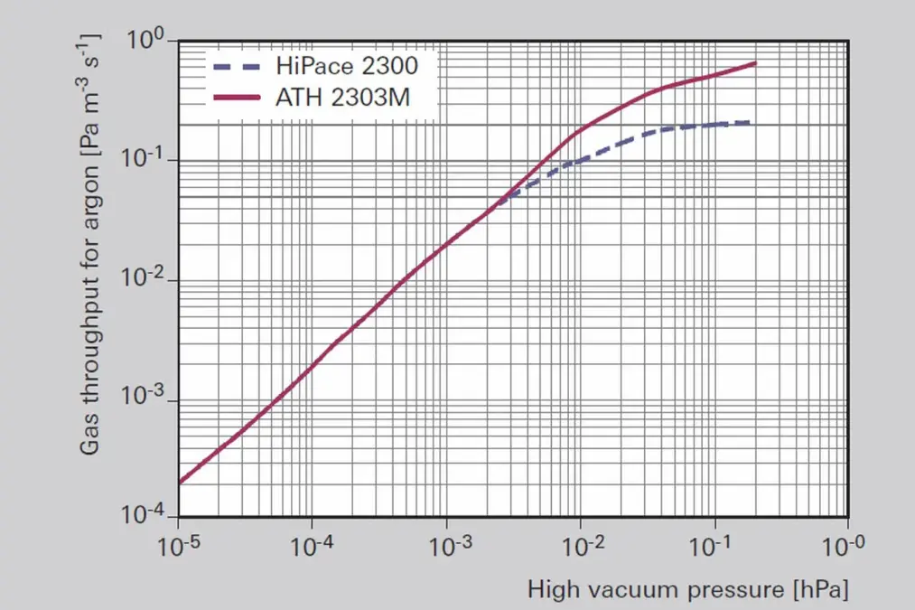
In Figure 2.7 the gas throughput graphs for different turbopumps with a NW 250 flange are given. The backing pump for the ATH 2303 is from a typical process-capable Roots pumping station as used in the semiconductor industry. The throughput must be the same for both pumps, because the same gas flow will pass through both pumps successively:
The choice of backing pump affects the temperature balance of the turbopump. If the pumping speed of the backing pump is designed precisely so as to attain the turbopump's maximum fore-vacuum compatibility with its gas throughput, then the turbopump rotor will be thermally loaded. A backing pump with a higher pumping speed should be selected to reduce gas friction and the thermal load on the turbopump.
The pumping speed at the process chamber is restricted to the required level either through the RPM or a regulating valve. Pressure regulation using the speed of rotation of the turbopump is hampered by the high inertia of the rotor which prevents a faster variation of the rotation speed. In some process windows it is possible to control the pressure by regulating the speed of rotation of the backing pump.
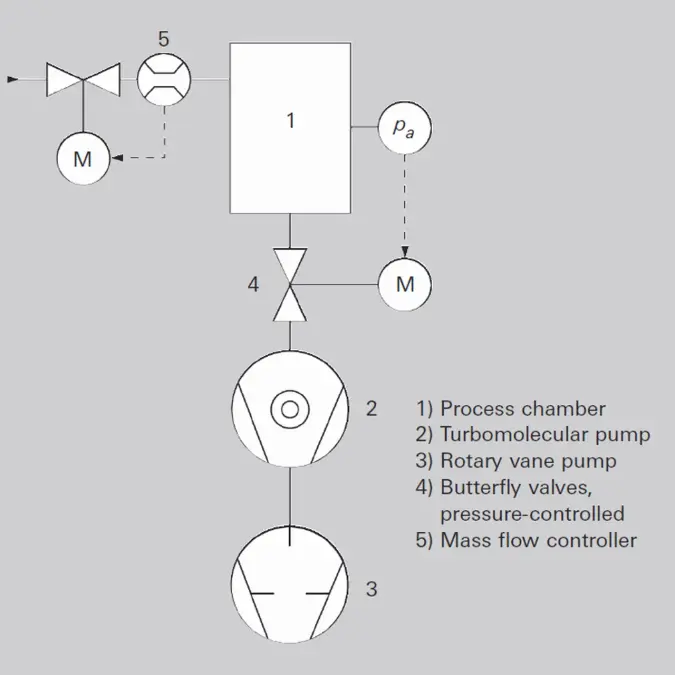
Let us take as an example a vacuum process system as shown in Figure 2.8 with the parameters Q =3.0 Pa m3s-1, process gas argon pprocess=5 Pa
Where S=\frac{Q}{p_{process}} we obtain a nominal pumping speed for the turbopump of 600 l s-1. At this high process pressure it is not possible to attain the maximum pumping speed for turbopumps. We therefore select a turbopump (2) of type ATH 2303 M which still attains a pumping speed of more than 800 l/s with a splinter shield at this pressure and a backing pump of type A 603 P. With this process pump we reach fore-vacuum pressure of 3.0 Pa with a gas throughput of 0.24 hPa m3 s-1. With a maximum turbopump fore- vacuum pressure of 3.3 hPa, this configuration is conservative despite the thermally demanding process gas argon.
The process gas is admitted to the chamber (1) via a mass flow controller (5). The butterfly valve (4) that is controlled by pressure pprocess throttles the pumping speed of the turbopump (2). After the conclusion of the process step, the gas supply is shut off and the control valve opens completely evacuate the chamber until the final pressure is reached. As this is happening, a new workpiece is loaded into the process chamber. Further information relating to pumping high gas loads as well as corrosive and abrasive substances is provided in Chapter 4.8.3.