Formula 6-5: Quadrupole deflection voltage
At this point, only a brief phenomenological description of the operating principle will be provided. For a more detailed description, please refer to the special literature [29, 30, 31].
-
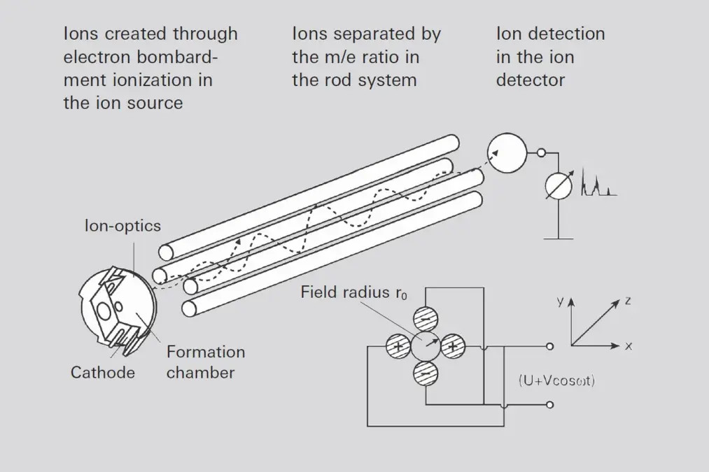
Figure 6.5: Quadrupole deflection voltage

Ideal quadrupole fields require rods that have a hyperbolic profile. In actual practice, however, cylindrical rods are used, with the rod radius being equal to 1.144 times the field radius r0 (refer to Figure 6.5 for a definition of the field radius). An electrical quadrupole field is formed between the rods. Ions of varying mass are injected axially into the rod system at approximately equal energy and move through the rod system at uniform velocity. The applied quadrupole field deflects the ions in the X and Y directions, causing them to describe helical trajectories around the Z axis through the mass filter. If the amplitude of the trajectory oscillation is smaller than field radius r0, the ions reach the detector; if the amplitude exceeds this the ions will discharge on the rods or the surrounding surfaces and will not pass through the filter.
To solve the equations of motion, two dimensionless variables a and q are introduced which combine the parameters of the quadrupole (DC voltage U, AC amplitude V, field radius r0, angular frequency ω=2πf) and that of the ion (charge Q=z⋅e, mass m=M\cdot m_{u} ).
To solve the equations of motion, two dimensionless variables a and q are introduced which combine the parameters of the quadrupole (DC voltage U, AC amplitude V, field radius r0, angular frequency ω=2πf) and that of the ion (charge Q=z⋅e, mass
Formula 6-6: Stability parameter a
and
Formula 6-7: Stability parameter q
With this simplification, Mathieu’s differential equations are obtained, the solutions for which are well-known in mathematics; they can be used to calculate the range of stable trajectories with oscillation amplitudes
r_{max} <
r_0 for pairings of stability parameters a and q located under the triangle formed by the two limiting curves in Figure 6.6. All solutions outside this range result in increasing oscillation amplitudes and thus in neutralization of the ions on the quadrupole filter rods. Dividing the two equations by one another gives:
a/q=2U/V . This is the slope of the so-called load line of the mass filter.
-
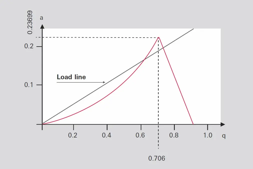
Figure 6: Stability diagram of a quadrupole filter

At the limit the load line intersects the peak with the values: ap= 0.237 and qp= 0.706..The quadrupole filter is transparent only for voltage ratios
\frac{U}{V}=\frac{a_{p}}{2\cdot q_{p}} .i.e. where the load line intersects the stability range. All ions whose parameters a and q are located in the triangle above the load lines will reach the detector.
Introducing the ratio mu/e between the atomic mass unit mu = 1.6605 · 10-27 kg and the elementary charge e = 1.6022 · 10-19 A · s ein ( m_{u}/e = 1.0365 · 10-8 kg A-1 s-1) and multiplying this by the dimensionless mass number M of the corresponding ion obtains the following conditions for voltages Up and Vp for the apex of the stability triangle (with the constants ku = 1.2122 · 10-8 kg A-1 s-1 and kv = 7.2226 · 10-8 kg A-1 s-1):
Introducing the ratio mu/e between the atomic mass unit mu = 1.6605 · 10-27 kg and the elementary charge e = 1.6022 · 10-19 A · s ein (
Formula 6-8: Stability condition U
Formula 6-9: Stability condition V
The stability conditions show that at a fixed frequency, there is a direct proportionality between the voltages and the masses at the quadrupole filter and that a linear mass scale is obtained with varying voltage amplitudes.
With the DC voltage shut off U = 0, all trajectories of the ions where q < 0.905 will be stable; according to Formula 6-3 these will be all masses where
With the DC voltage shut off U = 0, all trajectories of the ions where q < 0.905 will be stable; according to Formula 6-3 these will be all masses where
Formula 6-10: High-pass condition
Where kH = 1.0801 · 107 A s kg-1 is a constant. The filter thus acts as a high pass in this operating mode. As the RF amplitude V increases, ever-heavier types of ions become unstable, starting with the light masses, and are thus separated out. This operating mode produces an integral spectrum and allows a total pressure measurement to be carried out.
The ion injection conditions are crucial for transmission of ions through the filter. Ions must enter the quadrupole in an area as close as possible to the center of the rod system and ideally move parallel to the axis of the rod.
The greater the field diameter (distance between rods) and the longer the quadrupole (rod length), the easier it is to fulfill these conditions. In addition, the geometric accuracy (production tolerances) is easier to achieve the greater the rod dimensions.
Pfeiffer Vacuum ion sources described in 6.1.4.1 translate into high transparency and thus high sensitivity.
In practical operation, the ratio U/V s activated as a function of the mass number in such a manner that the actual resolution M/ΔM, does not remain constant, but that instead the line width ΔM remains constant. This means that resolution increases proportionally to the mass number. Due to Formula 6-9 (V is proportional to M) the quadrupole (as opposed to the sector field mass spectrometer) produces a linear mass scale. One point of major significance for a QMS is the required RF power. If C is used to designate the overall capacity of the system and Q dto designate the quality factor of the power circuit, the required RF power will increase
Formula 6-11: RF power
with high powers of f and r0. An enlargement of field radius r0 will lessen the relative mechanical tolerances that occur, thus resulting in improved behavior. Essentially, it is advantageous to select f0 and r0 as large as possible. However there are limits to this due to the associated increase in RF power according to Formula 6-11. While extending the rod system permits a lower operating frequency, the size of a production unit should not exceed certain practical dimensions.
The required mass range and desired resolution are governed by the dimensions of the filter and the operating frequency selected. Devices with 6, 8 and 16 mm rod diameters and appropriately matched electronics are available to satisfy the satisfy most requirements.
What follows is a brief digression on the relationship between resolution and mechanical precision. Let us consider a quadrupole mass filter that works at the apex of the stability diagram; i.e. with high resolution. The following equation applies Formula 6-8:
U= 1.2122 · 10-8
\frac{\mbox{kg}}{\mbox{A}\cdot\mbox{s}}\cdot M\cdot r_0^2\cdot f^2
for the DC amplitude and Formula 6-9
V= 7.2226 · 10-8
\frac{\mbox{kg}}{\mbox{A}\cdot\mbox{s}}\cdot M\cdot r_0^2\cdot f^2
for the AC amplitude. Here, Mdesignates the mass of the ion, r0 the field radius and f the frequency at which the filter is operated. We are making the idealized assumption that both voltages U and V, as well as frequency f, can be set and maintained “as precisely as desired.”
It follows from this that: M=c_{k}\cdot\frac{1}{r_0^2}
(ck is a constant) and following differentiation, division by M and determination of the value, the filter scatter caused by r0 is:
It follows from this that:
(ck is a constant) and following differentiation, division by M and determination of the value, the filter scatter caused by r0 is:
Formula 6-12: Scatter
Let us assume that the field radius r0 changes by dr0 = 0.03 mm over the length of the mass filter. Now let us consider the effect of this change on the scatter for two mass filters of different sizes. For optimal transmission, the resolution set on the spectrometer (we select: ΔM/M= 1/100), must be greater than the scatter generated by the fluctuation of r0. For a filter with a field radius of 3 mm, this results in dM/M = 2 · 0.03 mm / 3 mm = 0.02, i. e. the scatter due to the imperfect geometry hinders the desired resolution. For a different filter with a larger field radius of 12 mm, this results in dM/M = 2 · 0.03 mm / 3 mm = 0.005, the geometry does not hinder the desired resolution. In other words: if a resolution of ΔM/M = 0.01 has been set for both filters, then in the first case most of the ions will not be able to pass through the filter. In the case of the large filter for the second quadrupole, all ions will be able to pass through the filter.
Although this simplified error calculation by no means takes into account all of the effects that can contribute to transmission, it does demonstrate several fundamental relationships:
Although this simplified error calculation by no means takes into account all of the effects that can contribute to transmission, it does demonstrate several fundamental relationships:
- The larger the dimensions of the rod system are selected, the lower the influence of the absolute mechanical tolerances will be.
- The higher the mass range within which adjacent masses should be differentiated, the stricter will be the requirements relating to the relative accuracy of the mass filter.
Summary
A quadrupole mass filter is a dynamic mass filter for positive and negative ions. The mass scale is linear to the applied amplitude of the RF voltage. Mass resolution can be conveniently and electrically set by means of the ratio between the DC voltage U and the high-frequency voltage amplitude V Due to their compact dimensions and light weight, quadrupole mass spectrometers are suitable both as pure residual gas analyzers and, in higher-quality design, as sensors for gas analysis.6.3.2 Ion sources
Before gases can be analyzed in a mass filter, they must first be ionized in an ion source by means of electron bombardment (Figure 6.6). Electrons are emitted from an electrically heated cathode (filament). A voltage is applied between anode and cathode, which accelerates the electrons. Neutral gas molecules that are present in the formation space between the anode and cathode are ionized by collisions between electrons, forming single and multiple positive ions. The energy of the colliding electrons exerts a significant influence on both the number and type of ions that will be formed.-
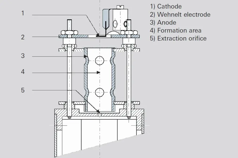
Figure 6.6: Ionization as a function of electron energy

Ionization of the neutral particles commences at a minimum electron energy of between 10 and 30 eV (appearance potential). The number of formed ions quickly increases as electron energy rises (acceleration voltage), reaches a maximum at 50 to 150 eV depending upon the type of gas in question, and slowly declines again as energy continues to rise. Since the yield in ions, and thus the sensitivity of the mass spectrometer, should be as large as possible, electron energies between 70 and 100 eV are typically used.
-
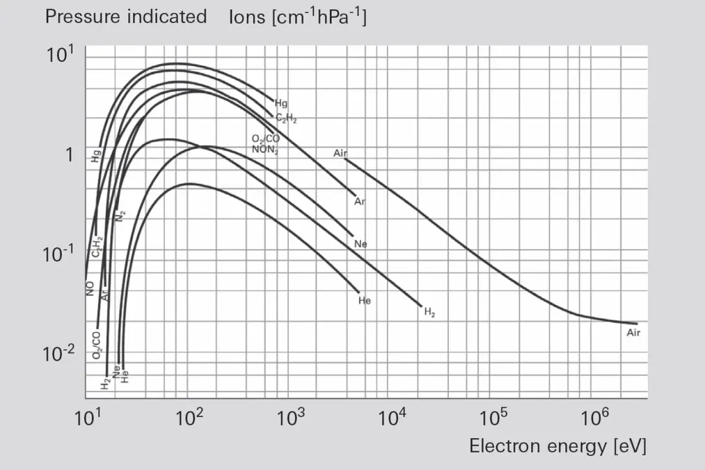
Figure 6.7: Ionization as a function of electron energy

The ion current IK+ of a gas component K can be calculated from the following relationship:
Formula 6-13: Ion current
Where:
Many types of ions are formed when ionizing complex molecules. In addition to single- and multiple-charge molecule ions (ABC+, ABC++) fragment ions also occur:
In addition to these types, it is also possible for recombination ions, such as AC+, to form. The occurrence and relative frequency of individual types of ions are characteristic of a certain type of molecule and serve as an important aid in identifying the molecule, and thus as an aid in qualitative gas analysis. Figure 6.8 shows the fragment ion distribution (cracking pattern or fragment pattern) of the simple molecule CO2, recorded at 70 eV of electron energy.
- i¯ electron current (emission current), in A
- Ie mean path length of the electrons, in cm
- s differential ionization effect cross section of K, in 1/(cm · hPa)
- pK partial pressure of the gas component K, in hPa
Many types of ions are formed when ionizing complex molecules. In addition to single- and multiple-charge molecule ions (ABC+, ABC++) fragment ions also occur:
- ABC+ 2e-
- ABC++ + 3e-
- AB+ + C + 2e-
- BC+ + A + 2e-
- A+ + BC + 2e-
- C+ + AB + 2e-
- B+ + A + C + 2e-
In addition to these types, it is also possible for recombination ions, such as AC+, to form. The occurrence and relative frequency of individual types of ions are characteristic of a certain type of molecule and serve as an important aid in identifying the molecule, and thus as an aid in qualitative gas analysis. Figure 6.8 shows the fragment ion distribution (cracking pattern or fragment pattern) of the simple molecule CO2, recorded at 70 eV of electron energy.
-
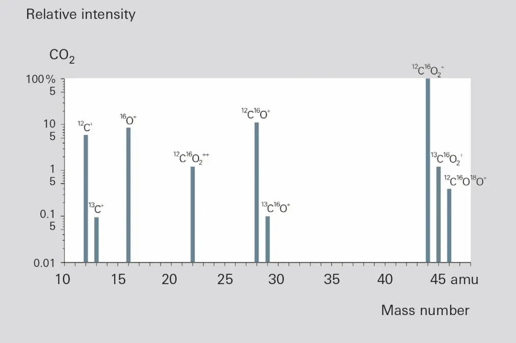
Figure 6.8: Fragment ion distribution of CO2

Selection of the ion source and the optimal filament material is based upon the requirements imposed by the measurement task. Applications often impose contradictory requirements on the ion source. In order to achieve optimal results, the ion source must be matched to the task in hand. This has resulted in the development of different types of ion sources that can almost all be equipped with cathodes made of rhenium (Re), tungsten or yttriated iridium (Y2O3/Ir).
Material | Temperature | Applicable gases | Remarks |
|---|---|---|---|
Y2 O3 / lr | 1,300 °C | Inert gases, air / O2, NOx, SOx | Short service life with halogens, insensitive to high O2 concentrations, generates some CO / CO2 from O2 or H2O background |
W | 1,800 °C | Inert gases, H2, halogens, freons | Short service life with O2 applications, generates some CO / CO2, from O2 or H2O background, C causes brittleness |
Re | 1,800 °C | Inert gases, hydrocarbons, H2, halogens, freons | Service life around three months due to vaporization of the material, used with hydrocarbons |
Table 6.1: Filament materials and their use
Tungsten (W) cathodes are preferred in the UHV range or where the vapor pressure of rhenium (Re) could have a disturbing effect. However the brittleness of tungsten cathodes due to the tungsten/carbon/oxygen cycle must be taken into account; i.e. due to the formation of W2C. Yttriated iridium is increasingly used today instead of the pure metal cathodes that were used in the past. The advantages offered by these cathodes are significantly lower operating temperature and relative insensitivity to air inrush. Consequently, the preferred fields of implementation for these cathodes are the analysis of temperature-sensitive substances, e.g. metal-organic compounds, or the analysis of contaminants in gas mixtures containing a high concentration of oxygen.
The various ion sources are described below on the basis of their attributes and fields of application. What all ion sources have in common is that they can be connected to a potential of up to 150 V. This avoids signal background due to EID ions ( EID = Electron Impact Desorption, also known as: ESD = Electron Stimulated Desorption). This technology will be explained in detail later.
The various ion sources are described below on the basis of their attributes and fields of application. What all ion sources have in common is that they can be connected to a potential of up to 150 V. This avoids signal background due to EID ions ( EID = Electron Impact Desorption, also known as: ESD = Electron Stimulated Desorption). This technology will be explained in detail later.
Axial ion source
This ion source is characterized by its extremely robust mechanical design and high sensitivity. It is primarily employed for residual gas analysis in high vacuum systems due to its open construction. Figure 6.6 shows a schematic diagram of an axial ion source. The cathode (1) is arranged within a hole in the Wehnelt electrode (2) and is connected with this electrode on one side. The electrons accelerated toward the anode (3) ionize gas molecules in the formation area (4). The positive ions reach the mass filter through the extraction orifice (5). Due to its relatively open construction, only minor falsification occurs through desorption and surface reactions.Grid ion source
A grid ion source is used to examine residual gas in UHV or even XHV applications. Its extremely open construction and the choice of materials ensure very low internal gas emissions. This ion source is equipped with two tungsten filaments that can be heated simultaneously for degassing. If work is to be performed at pressures below 10-11 hPa, rod systems that have been highly degassed especially for this purpose should be used. Measurements in the pressure range below 10-10 hPa can be falsified by so-called EID (electron impact desorption) ions [32]. These (H+, O+, F+, Cl+) ions are directly desorbed by electron bombardment of surfaces, often with a high yield. EID ions come from adsorbed coatings that originate earlier in the history of the UHV equipment or the ion source, and usually have an initial energy of several eV. This attribute is utilized by careful selection of the field axis voltage to suppress the EID ions relative to ions from the gas phase with an energy of approximately 100 eV (Figure 6.10).-
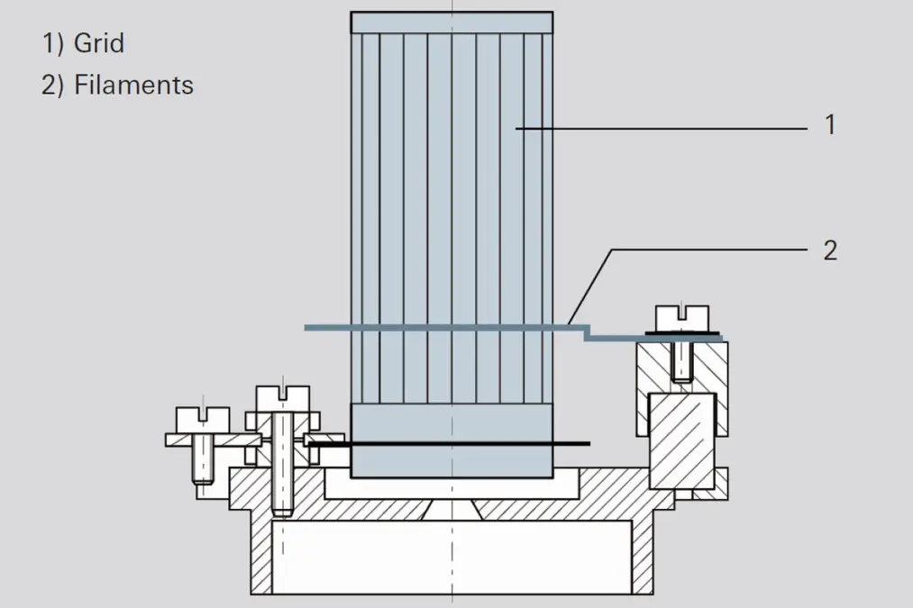
Figure 6.9: Grid ion source
-
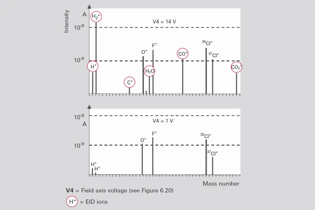
Figure 6.10: Discrimination of EID ions


Crossbeam ion sources
A crossbeam ion source (Figure 6.11) allows the direct passage of molecular beams perpendicular and parallel to the system axis. The system emits electrons with pre-selectable energy (0 – 120 eV) into the formation area (3), from either the left or the right filament (1). The Wehnelt cylinder (4) at filament potential prevents the electrons from scattering into the environment. Because the electron energy can be set within broad limits, this ion source can be used to determine the appearance potential. The crossbeam ion source very precisely maintains the entrance conditions of the ions into the mass filter. Crossbeam ion sources are used for diagnosing bundled molecular beams. In this process, the molecular beam is injected into the formation area perpendicular to the axis of the plane of projection (Figure 6.11). After passing through the ion source (7), non-ionized neutral gas molecules are either channeled into a pump or into a cold trap for condensation. Mass spectrometers with this type of ion source are also used as „rate meters“ for molecular beam epitaxy.-
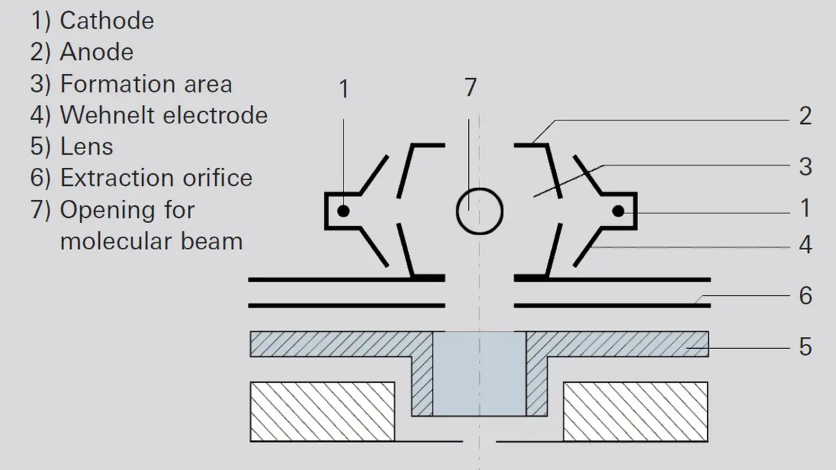
Figure 6.11: Crossbeam ion source

Gas-tight ion source
Some of the above-described ion sources are also available in gas-tight versions. Gas-tight ion sources are used if only small quantities of gas samples are available, or if the signal background generated by residual gas needs to be effectively suppressed. In this configuration, the gas inlet system (e.g. a heated capillary) and the ion source must be matched to one another. The inflowing gas volume will determine the pressure in the formation area, which can be a multiple of the pressure in the surrounding vacuum chamber, by means of the conductivity of the ion source. The operating principle will now be demonstrated using an axial ion source by way of example.The gas to be analyzed is introduced directly into the formation area (4) via a metal capillary (6) that is at ground potential and an insulating tube (5). Insulation is provided by the washer (7). The conductivity to the vacuum chamber is approximately 1 l/s.
-
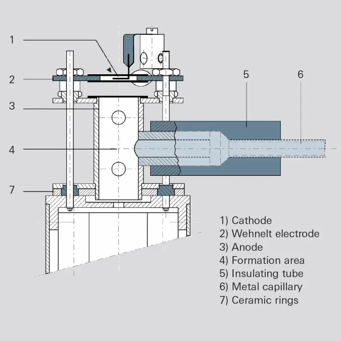
Figure 6.12: Gas-tight axial ion source

Sputter process monitor (SPM) ion source
In this ion source, the formation area (7) is connected directly with the process chamber. The analyzer is equipped with a small turbopumping station (1), which also evacuates the cathode space (5) to approximately 10-5 hPa. Electrons are injected into the formation area (7) from the low pressure side through small holes in order to ionize the gas. The ions thus formed are extracted to the mass filter through a small opening to the low- pressure side. This ion source offers two crucial advan- tages for examining the composition of the gas in sputtering processes. On one hand, the analysis is per- formed at an ion source pressure that is up to three orders of magnitude higher; i.e. a higher process pressure can be tolerated in the vacuum chamber. On the other hand, the hot filament is not in direct contact with the sputtering process. This avoids contamination by the hot cathode during sensitive processes.-
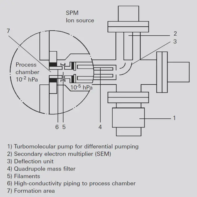
Figure 6.13: SPM ion source

Standard PrismaPlus ion source
The PrismaPlus mass spectrometer from Pfeiffer Vacuum is equipped with this robust and highly sensitive ion source. It is an ion source that is especially suited for residual gas analysis. Its design is comparable to that of a grid source, with two cathodes, resulting in reliable operation. Both an open version as well as a gas-tight version with gas inlet in the axial direction are available.-
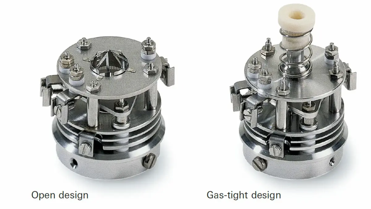
Figure 6.14: PrismaPlus ion sources

All ion sources described here ionize by means of electron impact. The ion sources can be categorized into two groups:
Closed ion sources are used in combination with a differentially pumped system (Figure 6.13) in order to analyze higher-pressure gases.
- Open ion sources are used if the gas to be analyzed is at high vacuum < 1 · 10-4 hPa.
- Closed ion sources are used in analytical applications, for example, where only small volumes of sample gas are available or to reduce background effects of the mass spectrometer vacuum system.
Closed ion sources are used in combination with a differentially pumped system (Figure 6.13) in order to analyze higher-pressure gases.
6.3.3 Detectors
The ions that are separated in the rod system on the basis of their mass-to-charge ratio can be electrically detected with various types of detectors:- By means of a Faraday cup for direct measurement of the ion current using an electrometer amplifier
- Using a secondary electron multiplier (SEM) of discrete design with individual dynodes
- By means of a continuous secondary electron multiplier (C-SEM)
Detector selection will primarily be based upon requirements that relate to detection sensitivity, detection speed and signal-to-noise ratio. However it will also be governed by other application-specific requirements that relate to stability, thermal and chemical resistance, as well as space requirements.
Faraday cup
In the simplest case, the ions strike a Faraday collector (Faraday cup), where they give up their electrical charge.-
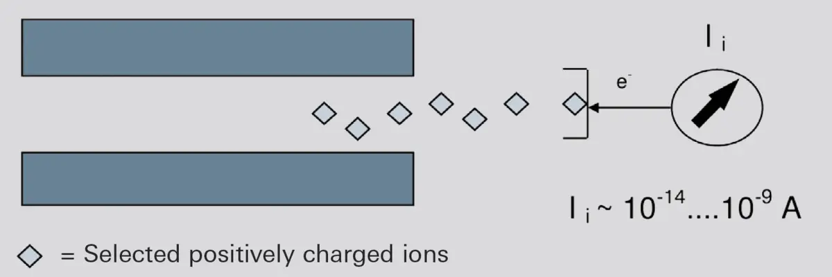
Figure 6.15: Operating principle of a Faraday Cup

The resulting current is converted to a voltage that is proportional to the ion current by means of a sensitive current-to-voltage converter (electrometer amplifier). The sensitivity of the electrometer amplifier with the Faraday cup is typically in the order of K= 10-4 A/hPa. The input resistance R of the current amplifier needs to be extremely high. With typical wiring capacities C this results in time constants
\pi=R\cdot C in the range 0.1 s < θ < 100 s. Depending upon the time constant, the measurement limit is between 1 · 10-16 and 1 · 10-14 A, and so minimal partial pressures in the order of pmin = 10-10 hPa can be detected. For UHV systems with total pressures of under 10-8 hPa this is usually.
In addition to its simple, robust design, a Faraday detector is characterized by its long-term stability and its ability to withstand high temperatures. To keep the time constants small and to avoid other interfering effects, the electrometer amplifier is connected directly to the analyzer and its output signal is supplied directly to the data analysis system. This is why the Faraday cup is also present in all Pfeiffer Vacuum mass spectrometers. It is, however, only suitable for detecting positive ions.
If extremely small ion currents are to be measured or if an extremely high measuring speed is required, physical pre-amplifiers, so-called secondary electron multipliers, are used.
Secondary electron multiplier (SEM)
Figure 6.16 shows the typical structure of such a multiplier (SEM = Secondary Electron Multiplier). Cylindrically shaped pieces of sheet metal (dynodes) are coated with a layer that affords a low level of electron work function. Depending upon its kinetic energy, an ion or an electron generates multiple secondary electrons upon striking this layer. Connecting multiple stages in series produces an avalanche of electrons from a single ion. Positive voltages of approximately 100 V are applied between the dynodes to accelerate the electrons. Technical implementation of this arrangement is produced by supplying a high voltage (approximately 1,000 – 3,000 V) to it by means of a resistance chain, with the individual dynodes being connected to the taps of this voltage. The positive high-voltage pole is grounded to keep the escaping electrons at approximately ground potential. These types of arrangements produce current amplification factors of 107.-
-sev_news_article_1200x675.webp)
Figure 6.16: Secondary electron multiplier (SEM) SEV
-sev_news_article_767x430.webp)
A secondary electron multiplier offers the following advantages over a Faraday cup:
However an SEM also has disadvantages:
Amplification changes as a result of these effects. Consequently, the SEM must be calibrated from time to time. Changes in amplification can easily be adjusted by modifying the high voltage. The conversion factor can be kept constant by supplying the first dynode with a separate high voltage that seeks to equal the energy of the various ions.
Extremely fast measurements are possible with the aid of secondary electron multipliers. As can be seen from Table 6.2, the measuring speeds are significantly higher than with a Faraday cup.
In addition to operation as current amplifiers, discrete dynode SEMs are also suitable as ion counters. Extremely low count rates of 1 ion per 10 s can be attained with this configuration. High count rates are also possible, producing an extremely broad dynamic range by comparison with operation as a current amplifier.
- It dramatically increases the sensitivity of the instrument, affording sensitivity increases of up to K = 10 A/hPa.
- This means that lower partial pressures can be scanned at shorter intervals of time with the downstream electrometer amplifier.
- The signal-to-noise ratio is significantly higher than that of an electrometer amplifier, which means that the detection limit can be lowered by several orders of magnitude. This applies only if also a lower dark current (noise level) can be achieved in the SEM at high amplification. An increase in sensitivity in its own right is of little value.
However an SEM also has disadvantages:
- Its amplification can change due to contamination or a chemical change in the active layer.
- The number of electrons (conversion factor) that generate a colliding ion (approximately 1 to 5 electrons) depends on the ion energy (mass discrimination).
Amplification changes as a result of these effects. Consequently, the SEM must be calibrated from time to time. Changes in amplification can easily be adjusted by modifying the high voltage. The conversion factor can be kept constant by supplying the first dynode with a separate high voltage that seeks to equal the energy of the various ions.
Extremely fast measurements are possible with the aid of secondary electron multipliers. As can be seen from Table 6.2, the measuring speeds are significantly higher than with a Faraday cup.
In addition to operation as current amplifiers, discrete dynode SEMs are also suitable as ion counters. Extremely low count rates of 1 ion per 10 s can be attained with this configuration. High count rates are also possible, producing an extremely broad dynamic range by comparison with operation as a current amplifier.
PrismaPlus | HiQuad with SEM 217 | HiQuad with SEM 218 | |
|---|---|---|---|
Detectors | Faraday / C-SEM | Faraday / SEM | Faraday / SEM with conversion dynode |
Maximum pressure for Faraday cup | 10-3 hPa | 10-4 hPa | 10-4 hPa |
Maximum pressure for SEM, C-SEM | 10-5 hPa | 10-5 hPa | 10-5 hPa |
Maximum measuring speed / u | 2 ms | 125 µs | 125 µs |
Bake-out temperature (max.) | 300 °C | 400 °C | 400 °C |
Counting operation | No | Yes (optional) | Yes (optional) |
Detection of positive ions | Yes | Yes | Yes |
Detection of negative ions | No | Yes | No |
Table 6.2: Detectors and their attributes
In the counting mode, the speed of the SEM defines the upper limit of the dynamic range. With a pulse width of 20 ns, non-linearity begins at a count rate of 106 events per second. Given its pulse width, the SEM must be suitable as a counter.
What all secondary electron multipliers have in common is that they are restricted to operating at pressures of less than 10-5 hPa. At higher pressures than these, the layer of water on the dynodes can lead to pyrolysis in operation, and thus to premature aging. Due to the high voltages involved, gas discharges that could destroy the SEM can occur at high pressures of p > 10-5 hPa.
What all secondary electron multipliers have in common is that they are restricted to operating at pressures of less than 10-5 hPa. At higher pressures than these, the layer of water on the dynodes can lead to pyrolysis in operation, and thus to premature aging. Due to the high voltages involved, gas discharges that could destroy the SEM can occur at high pressures of p > 10-5 hPa.
Continuous secondary electron multiplier (C-SEM)
A C-SEM (Figure 6.17) consists of a glass tube whose interior is coated with a conductive layer that has high resistance and a low work function. High voltage is applied to the layer in order to obtain a uniform voltage gradient throughout the length of the tube. Ions from the quadrupole system are routed to the conversion dynode and generate secondary electrons that trigger an electron avalanche in the tube. Current amplification factors of 106 are attained at an amplification voltage of 2,500 V.-
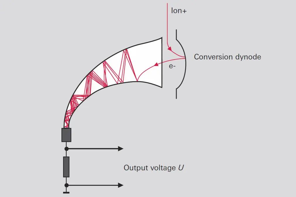
Figure 6.17: Operating principle of continuous secondary electron multiplier (C-SEM)

Here, too, amplification and dark current govern the signal-to-noise ratio, and the maximum current / dark current ratio of 106 is the current amplification factor. Thanks to a C-SEM arrangement that is slightly offset relative to the axis of the quadrupole, both a Faraday cup as well as a C-SEM can be used next to one another in the analyzer, with changeover from one detector to the other being possible when necessary.
6.3.4 Vacuum systems
The ions must be able to pass through the quadrupole filter without colliding with neutral gas particles. Mean path lengths which are attained at pressures p < 10-4 hPa are required for the operation of quadrupole mass spectrometers. This necessitates an appropriate pumping station with pressure monitoring. In order to perform gas analysis with optimal sensitivity, not only a low base pressure is necessary but the residual gas should contain only unavoidable partial pressures stemming from desorption from the walls of the equipment. Residual gas spectra of this type and low base pressures are best attained with turbo drag pumping stations (Figure 4.27). An additional total pressure gauge protects the mass spectrometer against being energized at excessively high pressures. When setting up such a system, attention must be paid to an appropriate arrangement of gas inlet, valves, pumps and measurement instruments in order to avoid falsification stemming from unfavorable flow conditions. A separate pumping station that evacuates the measurement system is often required during the course of vacuum processes that run at high pressure. Small pumping stations with turbo drag pumps and diaphragm pumps are used for this purpose.6.3.5 Inlet systems
Gases to be analyzed must usually be reduced from atmospheric pressure to pressures of less than the working pressure of the mass spectrometer (MS). Many vacuum technology processes that are monitored by mass spectrometers occur in pressure ranges p > 10-4 hPa. An essential element of a quadrupole mass spectrometer is therefore a suitable gas inlet system for the particular application. Various pressure reducing procedures are used, depending on the pressure gradient in question.Gas mixtures should be admitted to the mass spectro-meter without de-mixing if possible:
- At pressures p > 10 hPa, pressure is reduced by means of a (heatable) capillary, in which laminar flow prevails, with a downstream gas inlet valve. Under some circumstances, pressure reduction by means of an additional pump will be necessary.
- At pressures p < 10 hPa, pressure is reduced with an orifice and a mass spectrometer which is differentially pumped with a turbomolecular pump.
- At pressures p < 10-4 hPa the mass spectrometer can be installed directly in the process chamber with an open ion source.
Where an orifice is used for reducing pressure, its gas-type dependent conductivity is canceled out by the equally gas-type dependent conductivity of the flow path towards the pump, which means that the concentrations in the QMS reflect the true gas composition.
Inlet system | Pressure range | Product example | Characteristics |
|---|---|---|---|
No pressure reduction | 10 -12 to 10 - 4 hPa | PrismaPlus QMG 220, HiQuad QMG 700 | Open construction ion sources to allow gas from anywhere in the system to be represented in the ionizer volume. |
SPM ion source | 10 - 9 to 10 hPa | PrismaPlus SPM 220, HiQuad SPM 700 | Special ion source for analyzing sputter processes. This system analyzes gas directly at the sputter pressure of 10-2 hPa with no pressure reduction. |
Capillary inlet | 100 to 1,100 hPa, depending on the capillary length and the downstream orifice | OmniStar, ThermoStar, Inlet system GES 020 and GES 010 | Differentially pumped inlet system, low mass discrimination, not suitable for varying sample pressures |
Orifice inlet | 0.01 to 10 hPa, as a function of orifice diameter | PrismaPlus HPA 220 | Orifices with diameters of 0.01 to 0.5 mm, simple, robust design, mass discrimination, changing inlet pressure possible with various orifice diameters, not suitable for fast-changing gas compositions |
Dosing valve | 0.1 to 1,000 hPa | PrismaPlus HPA 220, Gas dosing valves UDV 040, UDV 146 | Dosing valves are suitable for gas inlets over a very broad measurement range, differentially pumped valves also allow analysis of rapidly changing gas compositions |
Pressure-regulated gas inlet | 10 - 3 to 1,000 hPa | EVR 016 with RVC 300, OmniStar with pressure-regulated inlet | Differentially pumped inlet system, comprising a control loop with regulating valve and pressure measurement, relatively large dead volume, slow response |
Table 6.3: Various gas inlet systems and their attributes
6.3.6 Application notes
Mass spectrometer analysis is every bit as varied as vacuum applications. The above-described gas inlet systems with heated capillaries are used for gas analysis in the pressure range of up to atmospheric pressure. Gas flows can be channeled directly to gas-tight ion sources in order to reduce the background noise of the vacuum environment. Gas beams are passed through crossbeam ion sources, with the beam exiting into a vacuum pump or trap.-
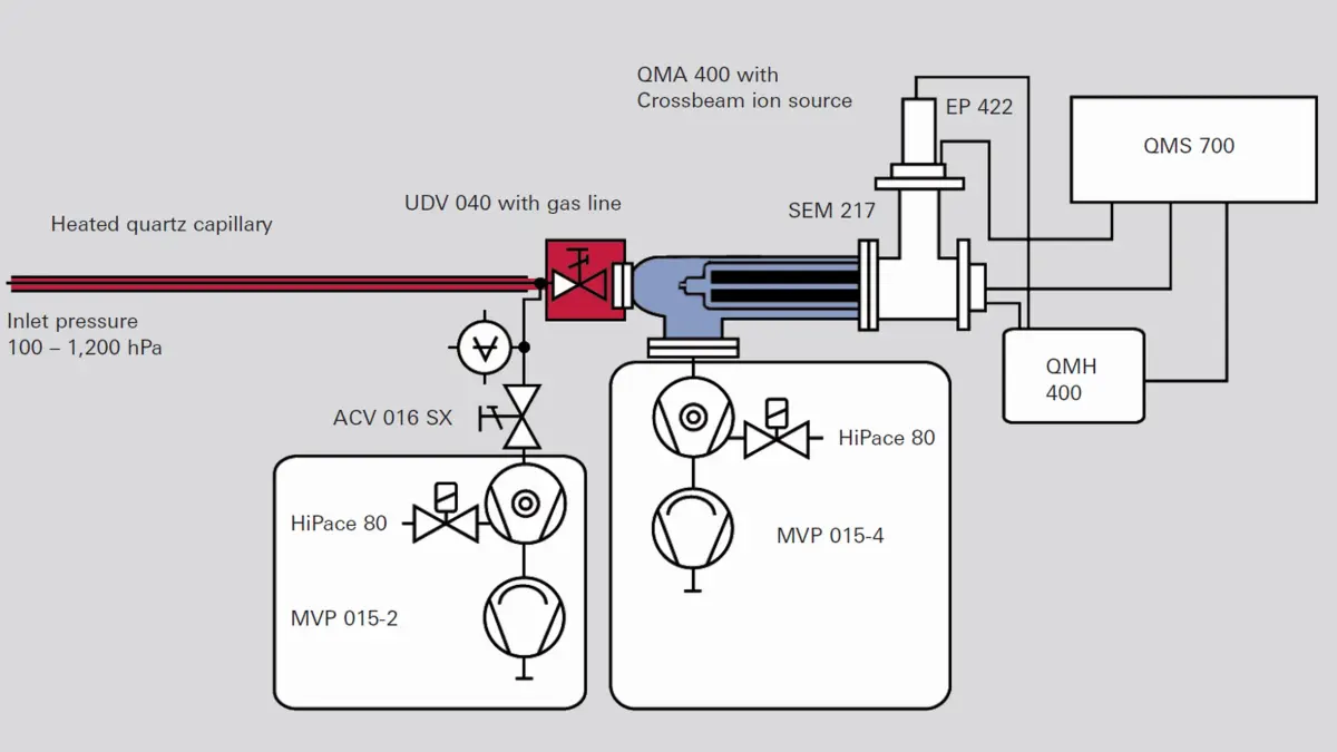
Figure 6.18: QMS with gas inlet system and crossbeam ion source
-
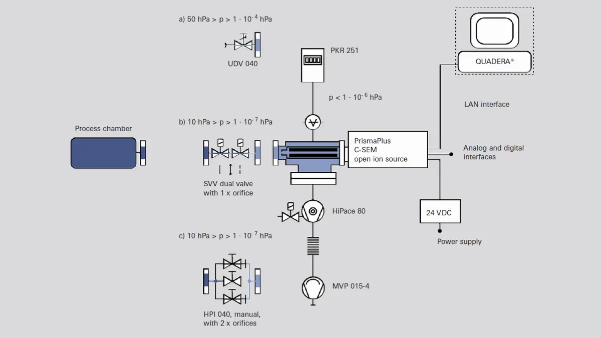
Figure 6.19: Differentially pumped QMS with various gas inlets


In the pressure range
p < 10 hPa (etching, sputtering or other coating processes), the gas is admitted into the mass spectrometer via an orifice or a valve. A turbopump is attached to the measuring system for pressure reduction. There are special versions for corrosive gases.
At extremely low pressures, particularly in the UHV range, open ion sources are used which have a particularly small surface area and therefore low outgassing rates (grid ion source). Due to the low gas densities, secondary electron multipliers (SEM) that are arranged perpendicular to the axis of the quadrupole must be used as detectors. To improve the signal-to-noise ratio, a turbopump that pumps down the inflowing neutral particles is attached opposite the SEM.
Secondary ion mass spectrometry (SIMS) represents a special case. In this process, ions are shot onto surfaces that in turn release positively or negatively charged secondary ions. These are detected directly by a QMS without an ion source. The measuring arrangement described in the preceding section is used in this case as well.