3.3.1.1 Welding
In vacuum equipment, components of mild and stainless steel are usually welded together for vessels and joints. In addition, it is also possible to weld aluminum components together. To ensure that the welds that are produced are vacuum-tight, it is necessary to use proper materials that are free of cracks and voids, and whose surfaces are smooth and free of grease. In addition, a special geometric design is also required that sometimes differs from the normal welded connections that are employed for non-vacuum applications. Wherever possible in terms of engineering, interior welds must be provided in order to avoid vacuum-side gaps and cracking, so-called latent or virtual leaks. If this is not possible, the weld must extend through to the vacuum side. Where necessary, a supplemental atmosphere-side weld can be employed to increase mechanical stability. In this connection, it is important that this supplemental weld not be continuous in order to allow leak detection, if necessary, and have no air inclusions.The welding of vacuum components and chambers requires special knowledge and the welding personnel must have a professional qualification. Usually, a welding company documents this with regular tests of their welders through independent testing institutes. In addition, welding procedure tests for each welded material and the weld geometry should be carried out. Specially trained welding personnel, for example welding engineers or technicians, accompany and evaluate the welding work.
The welding heat and the relatively rapid cooling can change the properties of materials. For example, changes in the structure during welding of austenitic stainless steels can increase the magnetizability or result in pores and hot cracks occurring during welding of aluminum (this was already mentioned in Chapter 3.2.1.1 “Stainless steel” and 3.2.1.3 “Aluminum”). In addition, high residual stresses in the weld area lead to the distortion of the components, which must be kept as low as possible. If functional areas like sealing surfaces are affected, they must be reworked. If this is not possible, it can lead to a loss of the entire workpiece. However, various welding measures can be taken to prevent this, including the selection of a suitable welding method combined with a suitable weld geometry and welding sequence, welding preparation and post-weld treatment, and not least the qualifications and experience of the welder.
In vacuum technology tungsten inert gas welding (TIG) is used often. In addition, other types of gas shielded metal arc welding are used as well as special methods, such as micro-plasma welding for thin-walled components or orbital welding for pipe components. Significantly more elaborate machine procedures are laser welding and electron beam welding. Both are suitable for delicate components and for deep welds. For welding of large aluminum valve housings, friction stir welding is used, which is an elaborate machine procedure with low welding distortions.
Tungsten inert gas welding (TIG) does not require a consumable electrode, and the joint parts can be welded directly without any additional materials. If additional welds need to be made, for example, for stability reasons, then welding consumables can be used. Other advantages of this method are virtually no spatter, no slag formation and versatility: stainless steel, aluminum and also copper can be TIG welded. The TIG method is preferred if a high quality weld is desired with respect to the welding speed.
-
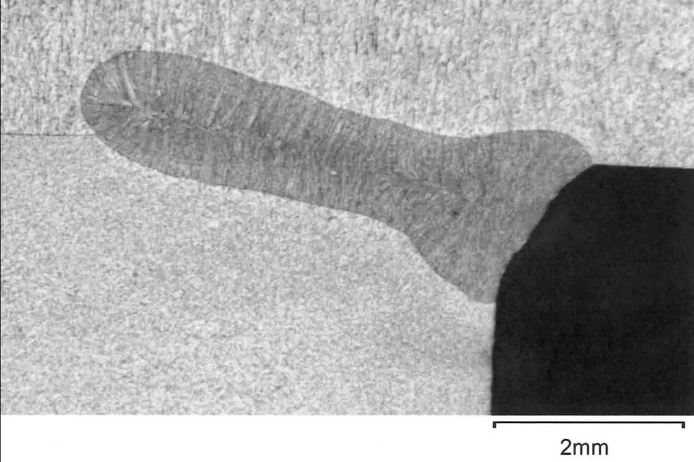
Figure 3.4: Cross section image of a laser weld
-
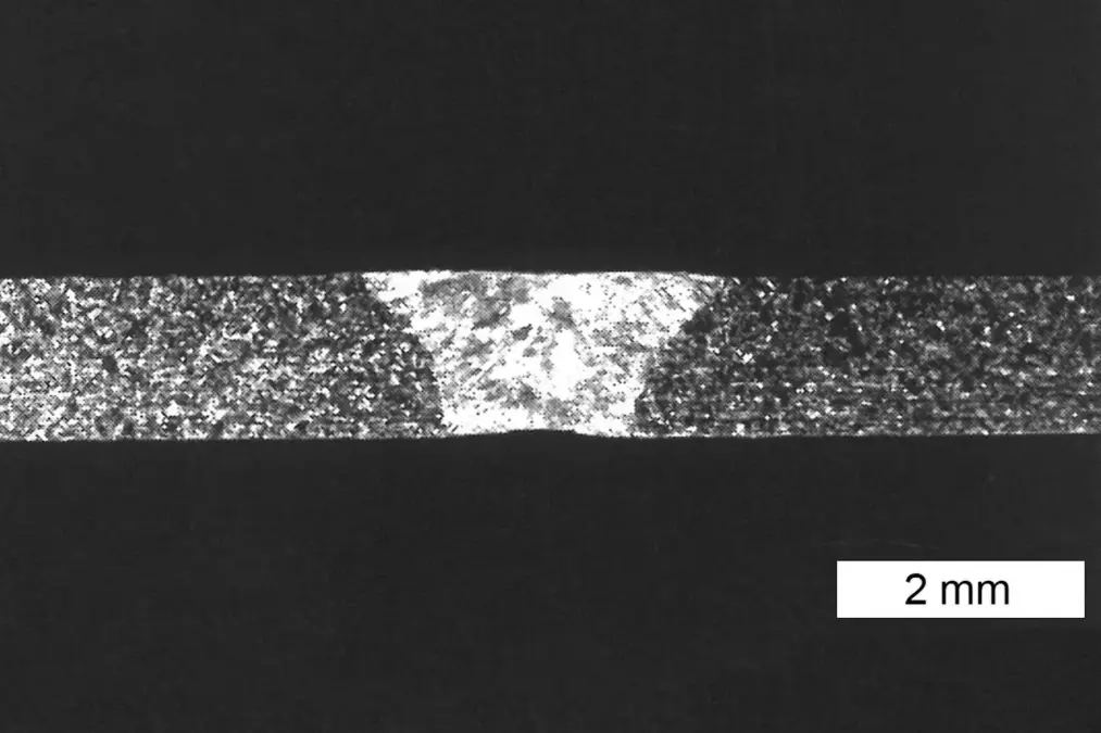
Figure 3.5: Cross section image of WIG orbital weld


Laser beam welding, or in short laser welding, is characterized by a high welding speed and low thermal distortion. The high concentrated energy input of the laser leads to a narrow weld zone and limits the range of the heat zone. Thin films, as well as deep and narrow welds for load-bearing structures can be created by setting the focus width and the laser intensity. That way, chamber components can be can designed without additional welds, or weld-on flange rings can be deep-penetration welded to pipe ends without the need for elaborate reworking of the sealing surface geometry. Larger gap widths at the joints can be bridged to a certain degree. Additional materials used are partially used here. A disadvantage are the high investment costs.
Orbital welding is a fully mechanized inert gas welding process that provides steady high seam quality, as the arc is lead mechanically and under controlled conditions around the pipes or the round component. The system expense is higher than for TIG welding. An orbital welding tong covers only a limited range of pipe diameters. Each tube outside diameter also requires a device suitable for holding the pipe.
During electron beam welding, accelerated, focused electrons provide the energy required in the weld zone. In order to prevent the scattering and absorption of the electrons, the process is carried out in a high vacuum. This also makes it possible to weld highly reactive materials. The high system price and the weld preparation with possibly a required equipment construction, it usually leads to high prices for the procedure and mainly restricts its use to series components.
After the welding of austenitic stainless steel a metallically smooth surface must be present again, so an even chromium oxide passive layer without interruptions can be formed. For example, an inert gas shielding (including for the root base) prevents scaling of the surface at temperatures above 600°C. Mechanical or chemical finishing followed by thorough rinsing removes discoloration on the surface and cleans the component.
3.3.1.2 Brazing, fusing and metallization
In addition to welding, the soldering process is also used to join metals. Soldered joints at soldering temperatures of above 600 °C are used almost exclusively in vacuum technology. In order to eliminate the need for highly corrosive flux when soldering, which often involves high vapor pressure, and in order to obtain oxide-free, high-strength joints, the soldering process is performed under vacuum or in a clean inert gas atmosphere. Soft solder joints are often not suitable for vacuum applications. They typically cannot be baked out, have less mechanical strength and in addition to tin, which has a low vapor pressure, frequently contain other alloy components with a high vapor pressure. Analogously to vacuum welds, a vacuum- brazed connection occurs when the following requirements in particular are met: carefully cleaned surfaces, careful formation of the soldering gap, use of a gas-free solder with a low vapor pressure, good flow and wetting properties of the solder (gap filling), a well-defined fusion zone of the solder and low reaction between the soldering and the base material. The standard brazing alloys can be divided into two major groups: Brazing alloys based on noble metals (mainly silver) and nickel-based brazing alloys. The structured noble metal-based low-melting brazing alloys are significantly more expensive than the higher-melting nickel base. Therefore, it is preferable to use nickel-base alloys, if this is technically possible and if a higher processing temperature is acceptable. The arrangement of the components to each other and the solder gaps between them must match the soldering process. Depending on the nature of the solder used, the soldering temperature and the thermal expansion of the components, the solder gaps (at room temperature) are typically 0.03 to 0.1 mm. The question of when welding and when brazing should be used, cannot be answered in a general and comprehensive way. Except in cases where welding is not possible, brazing can be advantageous if as many connecting points as possible can be produced simultaneously in a batch.The fusing process is primarily used for glass equipment and for glass-to-metal connections. Glass-to-metal fusings are especially important in the production of vacuum-tight current feedthroughs, for bakeable viewports and in the production of vacuum gauges. To fuse glass-to-metal transitions, the materials must be selected in such a manner that the thermal expansion coefficients of these materials are as similar to one another as possible throughout a broad temperature range. Since this is often not the case, numerous special alloys have been developed for so-called non-adapted glass-metal seals. In the form of a welded lip, they provide an elastic contact between glass and stainless steel for viewports. Fusings are difficult to perform with quartz glass, as it has a very low thermal expansion, which metal and metal alloys can nowhere near achieve.
Ceramic-to-metal connections are used for highly bakeable and highly insulating current feedthroughs. These are used among other things for the production of high-performance transmitting tubes and ceramic vacuum chambers for particle accelerator of the physical large-scale research. Connections with ceramic, e.g. aluminum oxide (92 % to 98 % Al203), are pre-metalized with those points to be joined with the metal. In this connection, it is particularly important to ensure that the thin metal layer (molybdenum or titanium) creates a thorough connection, free of voids and pores, with the ceramic substrate. For the production of electrical feedthroughs. a nickel layer is applied subsequently, to which a metal cap is brazed and a conductor is then soldered to.
3.3.2 Detachable flange connections
The individual components of a vacuum system, e.g. vacuum chambers, pumps, valves, measurement instruments, etc., are connected with one another either directly or by means of pipe components or resilient elements. The detachable interfaces between the components must be vacuum-tight. In configuring a vacuum system, however, as few detachable joints as possible should be used, as they represent a significantly more frequent source of potential leakage than non-detachable joints.Flange components from stainless steel, aluminum and steel can be used as connection elements. Metal hoses made of stainless steel are preferable to thick-walled rubber or thermoplastics for flexible joints. They are a strict necessity from the lower medium vacuum range onward.
From low to high vacuum ranges, ISO-KF flange connections with nominal widths of DN 10 to DN 50 are used for detachable connections, for larger nominal sizes of DN 63 to DN 1000 ISO-K and ISO-F flanges are used. Ultra-high vacuum compatible releasable connection, are in nominal widths DN 16 to DN 400 as a CF flange connection, respectively for larger nominal diameters of DN 400 to DN 800 flanges as a COF flange.
3.3.2.1 O-ring seals and grooves
When vacuum technology components are detachably joined, seals must be used to prevent ambient air from flowing into the vacuum. To prevent this, there are, depending on the application and pressure range different types of seals.O-rings are the most frequently used of all seals. They are available in different materials, usually elastomers with a hardness in the range of 65 to 80 Shore A. The unit Shore A is used for soft elastomers as a measure of malleability. The higher the number, the lower the deformation with the same applied force. The suitability of O-rings as good vacuum seals stems from their ability to adapt to the minute unevenness of the mating surfaces. The surface of the O-ring must be free of releasing grease or talcum, smooth and crack-free and scratch-free. The rings should be seamlessly pressed, the parting of the pressing tool should be on the level of the ring diameter and can be removed by grinding.
The O-ring can be coated with a thin film of a low vapor pressure grease (silicon grease, mineral oil-based or perfluoropolyether-based grease), depending upon the application in question. The vacuum grease smooth out small irregularities on the sealing surfaces and the surface of the O-ring and thereby improves, particularly at low degrees of deformation, the sealing effect. Here, the vapor pressure of the grease should be noted increases greatly with the temperature and should be well below the desired operating pressure. In addition, it must be examined whether components of the grease or low amounts of hydrocarbons are compatible with the application. In the case of dry installation, particular attention must be paid to surface quality, the cleanliness of the mating surfaces as well as to the sealing material. In addition, the degree of deformation should not be too small, to ensure good contact between the O-ring and sealing surfaces.
The cord diameter of the O-rings is usually 2 to 12 mm. The diameter for many connections is 5 mm resp. 5.33 mm in the area of the inch dimension. Generally speaking, O-rings are used as static seals. If dynamic stress is involved, precision O-rings that are manufactured especially for this purpose or alternatively mechanical seals or radial shaft seal rings, should be used.
O-rings can also be used in axial or radial grooves, in addition to being employed in conjunction with centering rings or sealing washers. In most cases, O-rings are placed in grooves and pressed between flanges, by generally using a combination of one flat flange and one grooved flange. The grooves must be carefully dimensioned. There are no generally accepted dimensions for this. The dimensions listed in the tables of O-ring suppliers are only reference values are used for orientation. They must be checked by the user on each specific application and suitability (e.g. through tests). Elastomers swell, shrink, harden or can even crack, due to external influences, such as temperature, pressure or reactions with the fluids used. This must be considered when selecting the elastomer and the groove. In addition, the sealing effect must be sufficient during each operating condition to ensure that the O-ring is not excessively compressed. If due to an increase in volume of the O-ring the groove is overfilled, it can damage the O-ring or even distort the flange.
For static sealing the maximum compression for a cord thickness of 5 mm should be about 25 %. Smaller diameters can be compressed more, larger diameters less. In practice, a compression of less than 15 %, in particular for dry mounting, can cause an insufficient sealing effect. The deformation force is mainly determined by the cord thickness and the hardness of the elastomer. To compress an O-ring of 5.33 mm thickness by 20 %, approx 5 N per mm of sealing length is required for a hardness of 70 Shore A resp. 7 N/mm for 80 Shore A.
To facilitate assembly, the diameter of the O-ring groove is usually selected somewhat larger than the diameter of the O-ring. This keeps the O-ring in the groove during assembly. Elastomer rings can safely be stretched in length by 5 %. The maximum stretch is dependent on the material and the operating conditions.
Elastomeric seals with trapezoidal or similar cross-sections can be used, for example, for valve seats and for lids and doors of vacuum chambers. The trapezoidal opening should be dimensioned such that the O-ring is not damaged when inserted and on the other hand is not pulled out when the valve plate is lifted or when you open the chamber door. In addition, with large contact forces, as they occur e.g. for large chamber doors, the trapezoidal-groove must allow enough room for the deformed O-ring, so that its deformation is kept within limits.
To seal screws, e. g. oil filler screws or oil drain plugs, the O-ring is installed in an angular position. The thread has a chamfer of 45 ° at the upper end, into which the O-ring is inserted and then compressed by the surface of the screw. The seal should be lubricated, so it is not damaged during tightening. In addition, the installation space must be greater than the volume of the O-ring.
Flat gaskets in combination with planar sealing surfaces are to be avoided in vacuum technology as much as possible. For this, a hard to reach high contact force is required, so that the sealing material fills any surface irregularities. If flat gaskets are used, this usually happens with circulating locally raised sealing surfaces, for example, with the combination of CF flange with a FKM flat gasket.
-
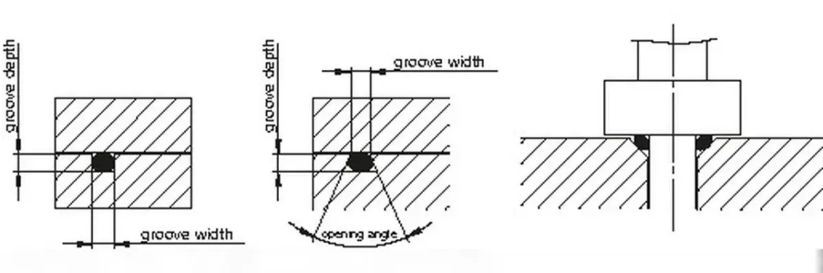
Figure 3.6: O-ring seals in rectangular groove, trapezoidal-groove and in an angular position

3.3.2.2 ISO-KF flange
ISO-KF small flange components are described in DIN 28403 and ISO 2861 in nominal diameters DN 10 to DN 50. The connections suitable for pressures up to 1 · 10-8 hPa and can be used for overpressures up to 1,500 hPa. With metal seals, the pressure range can be extended to less than 1 · 10-9 hPa. The significantly higher contact pressures required for this are created with special clamps for metal seals.An ISO-KF connection consists of two symmetrical flanges and one O-ring seal, which is positioned and supported with an internal or external centering ring (Figure 3.7). The necessary pressing force for the sealing is created by a clamping ring, which is placed over the conical tightening area and is tightened with a wing screw. This allows for a fast, efficient assembly and disassembly without any tools. The flanges can be aligned around its main axis in any direction.
For mounting a KF flange on a base plate, (Figure 3.8) claw clamps or bulkhead clamps are used as clamping elements. The dimensions of the bores in the base plate can be found in the product description of the claws and bulkhead clamps.
-
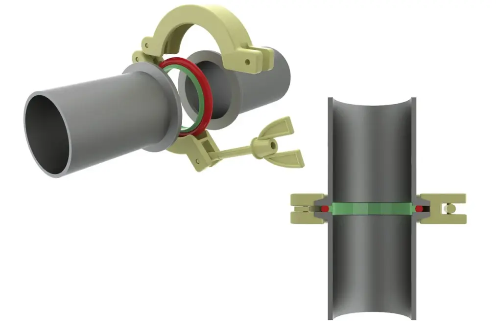
Figure 3.7: ISO-KF connection with centering ring and clamping ring
-
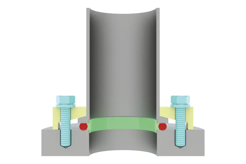
Figure 3.8: ISO-KF flange mounted on base plate with centering ring and claw clamps


3.3.2.3 ISO-K/ISO-F flange
ISO-K clamping flange components and ISO-F fixed flange components are described in DIN 28404 and ISO 1609 in nominal diameters DN 10 to DN 630 for ISO-K flanges and to DN 1000 for ISO-F flanges. The connections are suitable for pressures up to 1 · 10-8 hPa and can be used for overpressures up to 1,500 hPa. With metal seals, the pressure range can be extended to less than 1 · 10-9 hPa. Metal seals require significantly higher contact forces. Screwed flange connections provide that. If clamp screws are used, their number must be increased if necessary.An ISO-K and ISO-F compound consists of two symmet rical flanges and one O-ring seal, which is positioned and supported with an inner centering ring and also sup ported by an outer ring. The required contact pressure for sealing, is created with double claw clamps (Figure 3.9) or screws (Figure 3-13).
With ISO-K flanges, a circumferential outer ridge on the back of the flanges prevents slippage by the clamp screws. The flanges can be aligned around the main axis in any direction. Claw clamps are used for mounting an ISO K flange on a base plate. Depending on whether a centering ring is resting on the base plate (Figure 3.10) or an O-ring lies in base plate (Figure 3.11), claw clamps of different heights are used. Alternatively, the ISO-K flange can be screwed with a bolt ring onto the base plate (Figure 3.12).
-
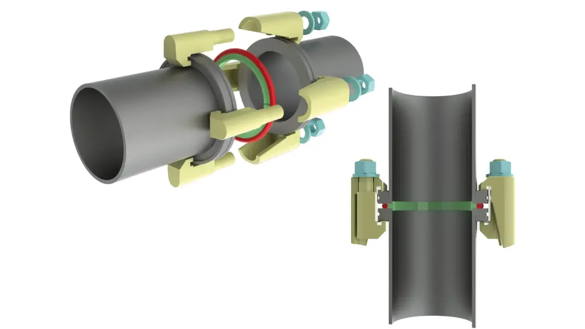
Figure 3.9: ISO-K connection with centering ring and double claw clamps
-
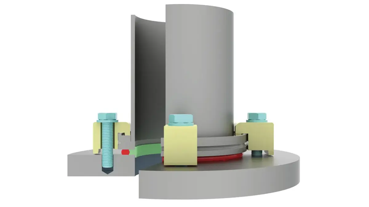
Figure 3.10: ISO-K flange mounted on base plate with centering ring and claw clamps
-
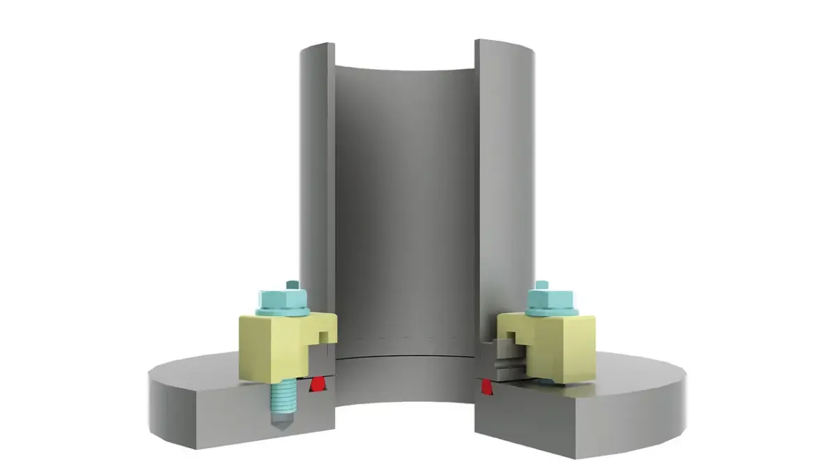
Figure 3.11: ISO-K flange mounted on base plate with O-ring nut and claw clamps for base plate with sealing groove
-
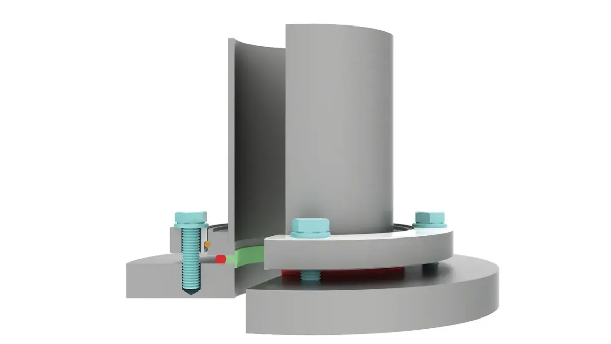
Figure 3.12: ISO-K flange mounted on base plate with centering ring, bolt ring and screws
-
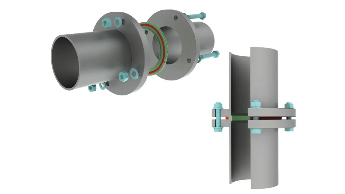
Figure 3.13: ISO-F connection with centering ring and screws


The ISO-F flange has a fixed bolt hole circle that is dependent on the nominal diameter. The flanges can be aligned with a hole spacing around the main hole axis. An ISO-F flange can be bolted onto a base plate. As a seal, a centering ring can be used or an O-ring with a sealing groove in the base plate.
Mounting an ISO-K flange on to an ISO-F flange can be done with a bolt ring (Figure 3.14). To install the bolt ring, it is slipped over the ISO-K flange and then a circlip is put into the outer circumferential groove of the ISO-K flange. The flanges can be aligned around the main axis in any direction.
Mounting an ISO-K flange on to an ISO-F flange can be done with a bolt ring (Figure 3.14). To install the bolt ring, it is slipped over the ISO-K flange and then a circlip is put into the outer circumferential groove of the ISO-K flange. The flanges can be aligned around the main axis in any direction.
-
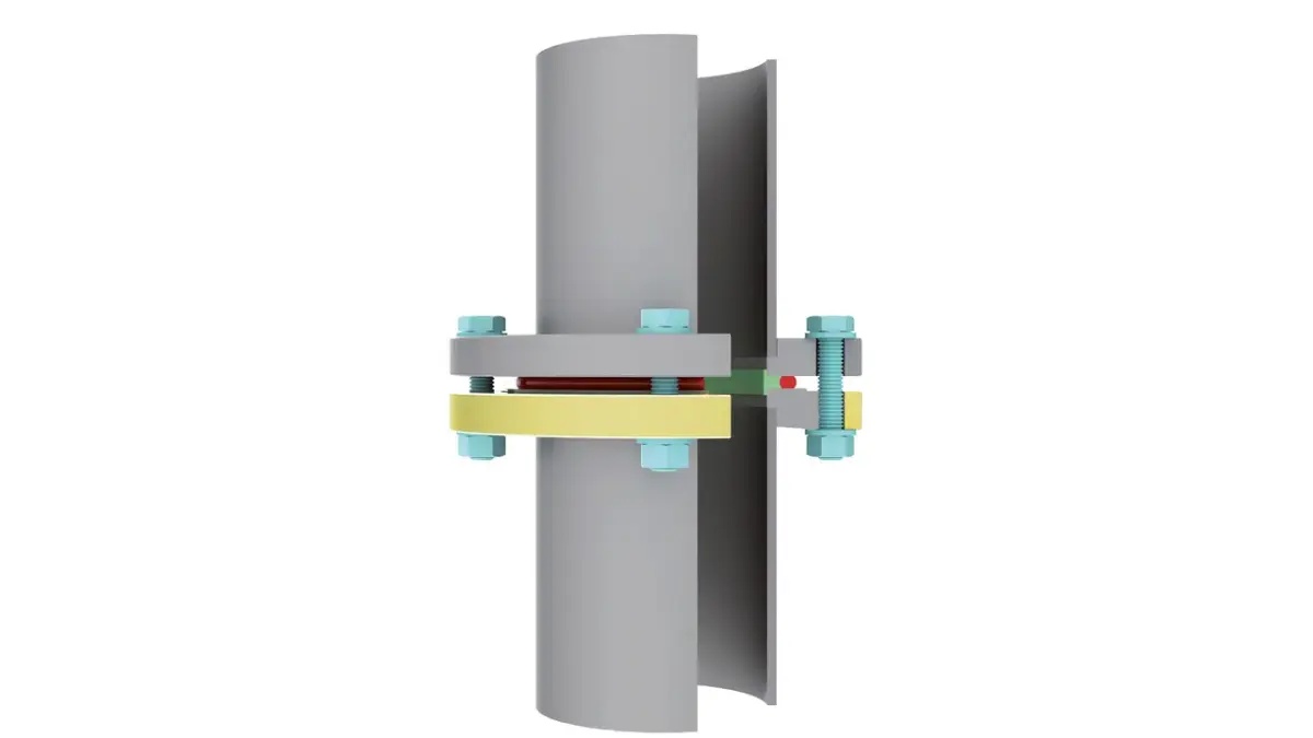
Figure 3.14: ISO-K flange with bolt ring mounted on ISO-F flange with centering ring and screws

3.3.2.4 CF flange
CF flanges are described in ISO 3669 in nominal diameters DN 16 to DN 250 and detailed in ISO/TS 3669-2 in nominal diameters DN 10 to DN 400 In addition to these standards, there are additional variants by manufacturers or users available on the vacuum market. For nominal diameters up to DN 250, they can often be combined. The larger nominal diameters are less common and differ considerably from each other. If there are doubts regarding the compatibility, the dimensions should be compared with each other.CF flanges were designed for UHV applications, are bakeable up to 450°C and suitable for pressures less than 1 · 10-12 hPa.The demands on the materials are relatively high. CF flanges are made almost entirely of stainless steel, generally with a low carbon content. The material 1.4307 is sufficient for many applications. For higher demands, for example, regarding the strength or a low magnetizability, the premium stainless steel 1.4429 ESR is recommended. For use on aluminum chambers, special bimetal flanges were developed, consisting of an aluminum base and a stainless steel surface or aluminum flanges that are equipped with hardened surface seal areas. In practice, however, their use often fails due to the relatively high price, the critical processability or the limited bakeability.
-
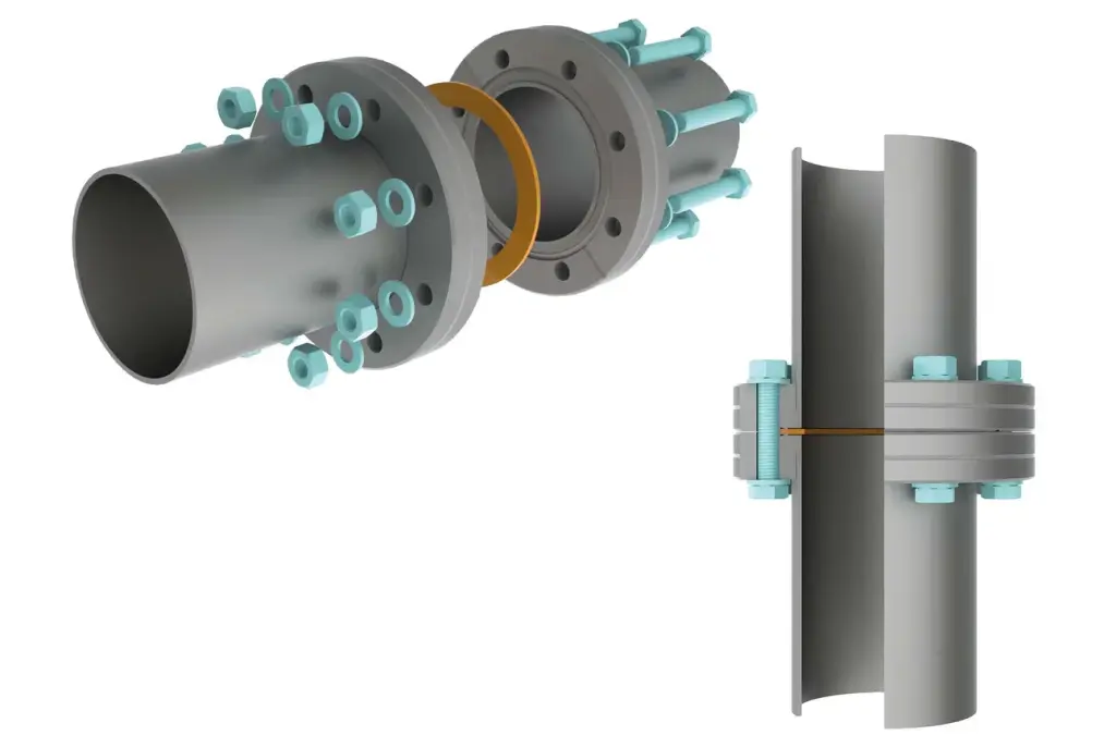
Figure 3.15: CF connection with copper flat gasket and screws

CF connection consists of two symmetrical flanges with cutting edges, a metal flat gasket, which is centered in a shallow groove and a sufficient number of screws, which provide the necessary high contact pressure (Figure 3.15). A radial recess on the flange is used for loosening the flange and it is useful for leak detection, as the helium can be sprayed directly onto the sealing surface. In addition to fixed flanges, which must be each aligned with a hole position, there is a design with a rotating collar flange, so that the flanges can be aligned in any direction around its main axis.
Oxygen-free copper OFCH (Oxygen Free High Conductivity) is generally used as a sealing material, for temperatures exceeding 200°C in a silver plated design. During assembly, the cutting edges of the flanges are pushed into the enclosed sealing disc. Extrusion takes place on the outer cutting edges and at the same time, on the inner edges a cutting operation takes place. The cold flow is limited by the outer vertical flange walls, so that very high pressures are created in the boundary layer. Under the high pressure, the copper of the microstructure adjusts to the cutting edges and to fills small surface defects, which creates a metal ultra-high vacuum-tight connection. Previously used copper gaskets cannot be reused. For pressures up to approx. 1 · 10-8 hPa, seals made of FKM can be used several times.
During assembly, the screws are initially tightened uniformly diametrically, to avoid any tension. Subsequently, the screws should be tightened in sequence, in several passes, step-by-step until the copper is connected to the sealing surface in a ultra-high vacuum-tight manner. When baking out, the heating and cooling should be smooth and not be too fast. Temperature differences at the flange connection lead to tensions that may damage the components, such as glass elements or may cause leaks.
3.3.2.5 COF flanges
COF flanges are used for large nominal diameters for ultra-high vacuum-compatible connections. They are bakeable, suitable for pressures up to approx. 1 · 10-12 hPa and not standardized, so that when combined with other-brand flanges, the compatibility must be tested. They are usually made of stainless steel with a low carbon content, if possible, in a forged quality.A COF connection consists of a pair of flanges with different “male” – and “female” profiles, a wire seal and a sufficient number of screws, which provide the required high contact pressure (Figure 3-16). The flanges can be aligned with a hole spacing around the main hole axis. A welded wire ring from oxygen free copper OF (Oxygen Free) is used as a sealing material.
-
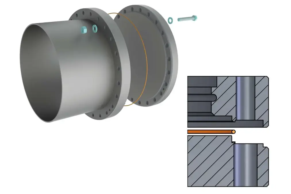
Figure 3.16: COF connection with copper wire seal and screws

During assembly, the seal is tightly inserted on the cutting edge of the “male” side. The sealing surfaces of the two profiles enclose the copper ring. A extrusion takes place on the cutting edges. The cold flow is limited by the vertical inner wall of the “male” flange, so that very high pressures are created in the boundary layer. Under the high pressure, the copper of the microstructure adjusts to the cutting edges and to fills small surface defects, which creates a metallic ultra-high vacuum-tight connection. Previously used copper wires cannot be reused. For pressures up to approx. 1 · 10-8 hPa, seals made of FKM can be used. They are usually not reusable, but allow faster assembly, for example, if flanges are mounted frequently, e.g. when leveling the system.
During assembly, it is important that the screws are initially tightened uniformly diametrically, to avoid any tension. Subsequently, the screws should be tightened in sequence, in several passes, step-by-step until the copper is connected to the sealing surfaces in an ultra-high vacuum-tight manner. When baking out, it must be ensured that the heating and cooling are smooth and not done too fast. Temperature differences on the flange connection lead to tensions, which may cause leaks.
3.3.2.6 Other flange standards
In addition to the listed vacuum flanges there are numerous other flange standards which are used, for example, in industrial and process engineering, but are not as widespread in vacuum technology. Often, their surfaces are rough and designed for flat seals. For systems that operate under vacuum and overpressure, vacuum flanges can only be used to a very limited extent. For this purpose, flanges according to EN 1092-1 are used, for example. To design flanges that are suitable for vacuum, the sealing surfaces must be reworked; for example, a flange with an O-ring groove and a flange with a smooth sealing surface are paired. Therefore, the relevant statutory regulations for pressure vessels and piping must be observed.3.3.2.7 Screws
The importance of screws in the design of metal-sealed connections, cannot be underestimated. Screws also have application limits before they break. Improperly installed screws are potential sources of risk for leaks, especially with cyclic thermal stresses.Two important mechanical factors must be considered when mounting screws: tensile strength Rm , which describes from which tensile stress upwards it results in screw breakage, and the yield point Rp 0.2, which indicates from which stress upwards the tension force remains the same for the first time or becomes less, despite increasing elongation of the screw. This represents the transition between the elastic and plastic range. Screws should not be subjected to stresses that are higher than the 0.2 % yield point Rp 0.2. The reference values for the tightening torque of screws are therefore values that take a 90 % utilization of the 0.2 % yield point into account.
The tensile strength and yield strength of steel screws at room temperature can be found in the specification under their strength classes, i. e. a two-digit number combination. The first number 1/100 [N/mm2] indicates the tensile strength. The multiplication of both numbers results in 1/10 [N/mm2] of the yield point. Example: strength class 8.8, Rm = 8 · 100 N/mm2 = 800 N/mm2, Rp 0.2 = 8 · 8 · 10 N/mm2 = 640 N/mm2.
In the designation of stainless steel screws, the material quality and the tensile strength are indicated. These are: A for austenitic,1 to 5 for the alloy type, and the strength class: -70 for strain hardened or -80 for high strength. The strength class equals 1/10 N/mm2 of the tensile strength. Example: specification A2-70, A2 equals austenitic, alloy type 2, 70 equals Rm = 70 · 10 N/mm2 = 700 N/mm2.
The nuts used, should have at least the same strength as the screws. For steel nuts, a number is indicated which equals 1/100 [N/mm2] of the test tension. Example: the number 8 equals Rm = 800 N/mm2. For stainless steel screws, a nut with either the same or a higher material quality and property class must be used. Caution: nuts, with a lower height than 0.8 times the screw diameter (flat design), have a restricted load- bearing capacity.
Type of screw | 0.2 % yield point Rp 0.2 [N/mm2] | Tensile strength Rm [N/mm2] | Material |
Stainless steel, A2-70 | 450 | 700 | Stainless steel, 1.4301, 1.4303, 1.4307 |
Stainless steel, A4-80 | 600 | 800 | Stainless steel, 1.4401 |
Steel, strength class 8.8 | 640 | 800 | Carbon steel, quenched and tempered |
Table 3.6: Mechanical characteristics and material of screws at room temperature
To determine the tightening torque and the preload stress, it is necessary to know the friction coefficient µtotal of the screw connection. Due to the variety of surfaces and lubrication conditions, it is impossible to provide reliable values. The scattering is too large. For this reason, only scattering ranges for the friction coefficient can be provided. To determine the correct torque, a test under operating conditions is recommended.
The friction coefficients can be reduced by the use of lubricants, however, the large scattering range remains the same. It should be noted that a smaller friction coefficient leads to a lower maximum torque. Hence: Use of lubricants → friction coefficient µtotal drops → less torque is necessary or may be applied.
For stainless steel screws, the friction values in the thread and on the supporting surfaces are substantially greater than with tempered steel screws. The scattering ranges of the friction values is also much larger (up to above 100 %). Due to the high edge pressure, they also tend to get stuck. A lubricant can generally help in this case. Alternatively, silver plated screws or nuts can be used.
Screw | Nut | µtotal without lubrication | µtotal with MoS2 paste | µtotal greased |
A2 or A4 | A2 or A4 | 0.23 – 0.50 | 0.10 – 0.20 | - |
Steel, electrolytically galvanized | Steel, electrolytically galvanized | 0.12 – 0.20 | - | 0.10 – 0.18 |
Table 3.7: Friction coefficient for stainless steel and zinc-plated steel screws
Properties of screws at elevated temperatures
When using screws at elevated temperatures, it must be noted that the tensile strength and yield point are reduced. In addition, the creep strain or heat resistance must be considered as a basis for assessing the mechanical strength. Therefore, information on yield strength serves only as a guide. For critical or safety-related applications and other mechanical parameters and all influencing factors must be considered.Type of scew | 0.2% yield point Rp 0.2 [N/mm2] at | ||||
20 °C | 100 °C | 200 °C | 300 °C | 400 °C | |
Stainless steel, A2-70 | 450 | 380 | 360 | 335 | 315 |
Stainless steel, A4-80 | 600 | 510 | 480 | 450 | 420 |
Steel, strength class 8.8 | 640 | 590 | 540 | 480 | - |
Table 3.8: Temperature dependence of the 0.2% yield point for stainless steel and steel screws with diameters ≤ M24
If a through-hole screw connection is tightened by the rotation of the nut, a tensile force is created in the threaded bolt and an equal compressive force between the plates. As a result, the screw is elongated and the component compressed. Through the elongation of the screw, the preload stress is created. The clamping force is produced by the compression of the parts, and without any additional force on the connection is the same size as the preload force.
During tightening of the screw, friction between the contact surfaces is created. With a growing preload force, the friction moments in the thread and the nut contact area increase. The maximum preload force represents the sum of the friction moments the majority of the total tightening torques. With lubricated screws (small friction coefficients) the friction proportion is lower, so that the screws produce a higher preload stress with the same tightening torque. It should be noted that the maximum permissible tightening torque with lubricated screws is lower than with non-lubricated screws.
Preload force and torque cause tensile and torsional stresses in the screw. Both influences must be simultaneously considered during the calculation of the screw load . An alternative for the calculation are tables, as they appear in the VDI guideline 2230. If a 90 % utilization of the 0.2 % yield point is considered acceptable, the maximum permissible tightening torque and the associated preload stresses for the different friction coefficients can be found there. However, the information only represents non-binding values for guidance. For critical or safety-related applications, all influencing factors that may be required for a screws calculation must be considered. Excerpts from the tables for stainless steel and steel screws are listed below.
Dimension and strength class | Max. tightening torque [Nm] for µtotal = | Max. preload force [kN] for µtotal = | ||||||||
0.10 | 0.14 | 0.20 | 0.30 | 0.40 | 0.10 | 0.14 | 0.20 | 0.30 | 0.40 | |
M4, A2-70 M4, A4-80 | 1.7 2.3 | 2.2 2.9 | 2.6 3.5 | 3.0 4.1 | 3.3 4.4 | 2.97 3.96 | 2.73 3.64 | 2.40 3.20 | 1.94 2.59 | 1.60 2.13 |
M5, A2-70 M5, A4-80 | 3.4 4.6 | 4.2 5.6 | 5.1 6.9 | 6.1 8.0 | 6.6 8.8 | 4.85 6.47 | 4.47 5.96 | 3.93 5.24 | 3.19 4.25 | 2.62 3.50 |
M6, A2-70 M6, A4-80 | 5.9 8.0 | 7.4 9.9 | 8.8 11.8 | 10.4 13.9 | 11.3 15.0 | 6.85 9.13 | 6.31 8.41 | 5.54 7.39 | 4.49 5.98 | 3.70 4.93 |
M8, A2-70 M8, A4-80 | 14.5 19.3 | 17.8 23.8 | 21.5 28.7 | 25.5 33.9 | 27.6 36.8 | 12.6 16.7 | 11.6 15.4 | 10.2 13.6 | 8.25 11.0 | 6.80 9.10 |
M10, A2-70 M10, A4-80 | 30.0 39.4 | 36.0 47.8 | 44.0 58.0 | 51.0 69.0 | 56.0 75.0 | 20.0 26.5 | 18.4 24.8 | 16.2 21.7 | 13.1 17.5 | 10.80 14.4 |
M12, A2-70 M12, A4-80 | 50 67 | 62 82 | 74 100 | 88 117 | 96 128 | 29.1 38.8 | 26.9 35.9 | 23.7 31.5 | 19.2 25.6 | 15.8 21.1 |
M16, A2-70 M16, A4-80 | 121 161 | 150 198 | 183 245 | 218 291 | 237 316 | 55.0 73.3 | 50.9 67.9 | 44.9 59.8 | 36.4 48.6 | 30.0 40.0 |
All data are approximate values for room temperature – see VDI 2230. For hexagon screws (ISO 4014 and 4017), hexagon socket screws (ISO 4762) and nuts (ISO 4032) with standard thread at a 90 % utilization of the 0.2 % yield point Rp 0.2.
Table 3.9: Maximum tightening torque and maximum resulting preload force for stainless steel screws
Dimension and strength class | Max. tightening torque [Nm] for µtotal = | Max. preload force [kN] for µtotal = | ||||
0.10 | 0.12 | 0.14 | 0.10 | 0.12 | 0.14 | |
M4, 8.8 | 2.6 | 3.0 | 3.3 | 4.5 | 4.4 | 4.3 |
M4, 8.8 | 2.6 | 3.0 | 3.3 | 4.5 | 4.4 | 4.3 |
M5, 8.8 | 5.2 | 5.9 | 6.5 | 7.4 | 7.2 | 7.0 |
M6, 8.8 | 9.0 | 10.1 | 11.3 | 10.4 | 10.2 | 9.9 |
M8, 8.8 | 21.6 | 24.6 | 27.3 | 19.1 | 18.8 | 18.1 |
M10, 8.8 | 43 | 48 | 54 | 30.3 | 29.6 | 28.8 |
M12, 8.8 | 73 | 84 | 93 | 44.1 | 43.0 | 41.9 |
M16, 8.8 | 180 | 206 | 230 | 82.9 | 80.9 | 78.8 |
All data are approximate values for room temperature - see VDI 2230. For hexagon screws (ISO 4014 and 4017), hexagon socket screws (ISO 4762) and nuts (ISO 4032) with standard thread at a 90% utilization of the 0.2% yield point Rp 0.2.
Table 3.10: Maximum tightening torque and maximum resulting preload force for steel screws of strength class 8.8
If screws are screwed into blind holes, an enclosed hollow space is created at the end of the threaded hole. Such dead volume is drained under vacuum only very slowly and leads to prolonged outgassing, which manifests itself in the same way as a leak. It is therefore also called a virtual leak. Under high vacuum and particularly UHV conditions, dead volume of this type should be constructively avoided or if that is not possible, it must be vented.
An alternative are vacuum screws which offer a comfortable means of venting. Their core has drilled holes (degassing bores). The screw head area has also a radial milling groove (degassing reduction), through which the area of the feedthrough hole of the screw connection is vented. The mechanical parameters for screws are not applicable to vacuum screws, as the vent hole leads to mechanical weakening.
An alternative are vacuum screws which offer a comfortable means of venting. Their core has drilled holes (degassing bores). The screw head area has also a radial milling groove (degassing reduction), through which the area of the feedthrough hole of the screw connection is vented. The mechanical parameters for screws are not applicable to vacuum screws, as the vent hole leads to mechanical weakening.