Please update your browser. It looks like you are using an old version of the Microsoft Edge browser. To get the best experience with the Pfeiffer website, please update your browser.

Contact Customer portal
Global
  • EN
  • DE
  • ZH
  • KO

3.7 Manipulators and mechanical feedthroughs

Many vacuum processes in research and industrial production require the movement of samples or components in the evacuated area. This can be linear position changes in the orientation of the three spatial axes and the revolution around the axis, as a single movement or as combinations of movement types among each other.

Manipulators and mechanical feedthroughs allow translations and rotations in the vacuum, their drive is located on the atmospheric side and the movements are transferred in a vacuum-tight way. Several different action and transmission principles are used, which are in accordance with the respective and vacuum and application conditions. Metallic membrane and spring bellows, special elastomer seals, magnetically coupled systems or differentially pumped seals can be used as sealing elements.

The designs with two open flange connections and an open passage are called manipulators, and components that have an actuator installed in a vacuum-tight flange are called mechanical feedthroughs. The latter are characterized by a compact design. Manipulators can be combined and extended among each other. In addition, mechanical feedthroughs can be attached to them, so that diverse types of movements transfer into the vacuum and with that provide solutions for various motion tasks. Additionally, other feedthroughs can be attached to the inlet flange, for example, for electricity or fluids and these can be guided by the manipulator directly to the application.

Especially with larger nominal diameters, the flanges of manipulators are under considerable forces due to the atmospheric pressure. So that the flanges are stable under vacuum, great emphasis must be placed on their inherent rigidity during the design of manipulators. The particular design challenge is to bring the highly precise transmission of movements in accordance with the external load and other loads by built-in components. The built-in components must be able to be baked out, in order to ensure the use even in the UHV range.
3.7.1 Operating principles

When selecting a suitable manipulator or a mechanical implementation, the user should know the underlying principle, to be able to assess the technical parameters regarding the suitability for its tasks.

3.7.1.1 Translation sealed by diaphragm bellows

Membrane bellows are made from individual lamellas welded together. With a small spring rate, the axial expansion is highly flexible. Bellows ensure a hermetically sealed metal enclosure and are suitable for the highest UHV requirements.

The selection and design of the bellows is in accordance with the required movement task, taking into account the operating conditions: Service life (number of movement cycles), operating temperature, bakeout temperature, differential pressures. The lifetime can be up to 0.5 million cycles with membranes made from the material 316L and up to 10 million movement cycles for the more elastic but magnetizable material 350AM.

Membrane bellows within the specified number of cycles are maintenance free. After they reach the calculated motion cycles they need to be replaced. They are not suitable for environments with dust and dirt.

Membrane bellows are used in the Z-axis, XY-axis and XYZ-axis precision manipulators, and port aligners and bellows sealed rotary feedthroughs.

When baking out units with diaphragm bellows, it is important to ensure an even heating. Heater bands on diaphragm bellows should be avoided. They lead to a strong local heating, as the diaphragm bellows have a low mass and a small area for the heat conduction. Temperature controlled heating sleeves are the better, though more elaborate alternative.

3.7.1.2 Bellows-sealed rotation

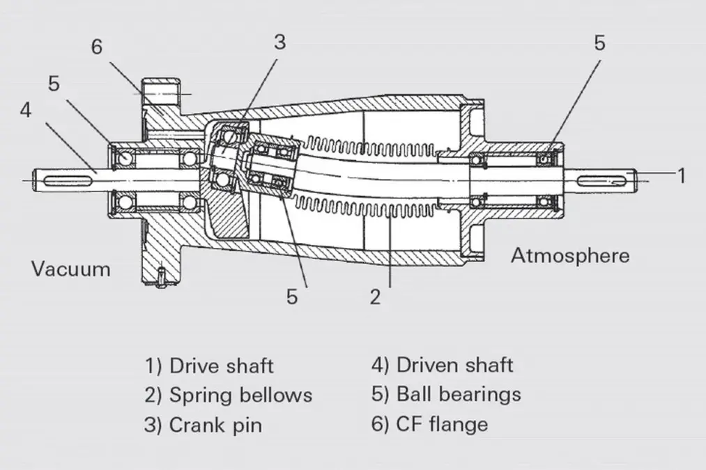
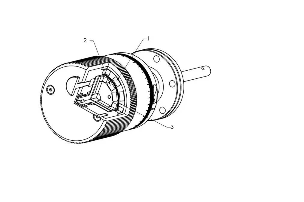
The so-called cattail or wobble principle allows the transmission of a rotational movement with bellows, i. e. rotary motion with a hermetic separation between vacuum and atmosphere. Figure 3.25 shows the design of such a feedthrough. The angled drive shaft (1), whose end is supported in a crank pin (3), rotates the drive shaft (4) in the vacuum. The hermetic seal consists of a non-rotating bellows seal (2) that performs a wobbling movement. Driven and drive shaft are supported by stainless steel ball bearings, which are coated with a vacuum-suitable dry-lubrication.
The dry lubrication increases not only the service life and possible maximum speed, it also prevents that the balls get stuck during the bake out at high temperatures. In addition to dry lubrication, hybrid bearings with ceramic balls can also be used for UHV applications. Their high price justifies a use only for the highest standards. Alter natively, for high vacuum applications that are resistant to small amounts of hydrocarbons, bearings can be lubricated with vacuum-suitable grease.

3.7.1.3 Magnetically coupled rotation and translation

Magnetic couplings are used for hermetically sealed rotary or linear feedthroughs. They consist of an array of permanent magnets on the outside that drive a rotor also equipped with magnets that can rotate/move in a vacuum. Both parts are completely vacuum sealed off from one another by a thin walled pipe. The distance between the magnets of the inner and outer rotor should be as low as possible, so that the coupling force between them is as large as possible. The rotor inside is connected to the application to be moved, the outer magnetic rotor is manually moved or motor-driven. The internal bearings are lubricated with a dry lubrication that are suitable for vacuums.

Often high-performance magnets made from metals are used for rare earths, such as samarium-cobalt magnets. They ensure highest possible coupling strength with simultaneously excellent resistance to high temperatures, such they occur during bake out. Such magnetically coupled systems are suitable for UHV applications. Even though the magnetic fields are shielded for the most part, the dispersion of the magnetic field lines cannot be avoided completely. The user must therefore check whether its application is sufficiently resistant to the residual magnetic field.
With magnetically coupled systems, rotational and linear motion and simultaneous rotation/linear motion can be implemented. The transferable displacement forces and torques are limited by the number of magnets and their arrangement. The achievable accuracy depends on the mass to be moved. The magnetic fields act as a spring between the two coupling partners. The higher the external force or torque, the greater the deviation of the position between the inner and outer rotors. If the external forces and moments are low compared to the maximum allowable values, the movements can be transferred very accurately.

3.7.1.4 Sealed elastomer rotation and translation

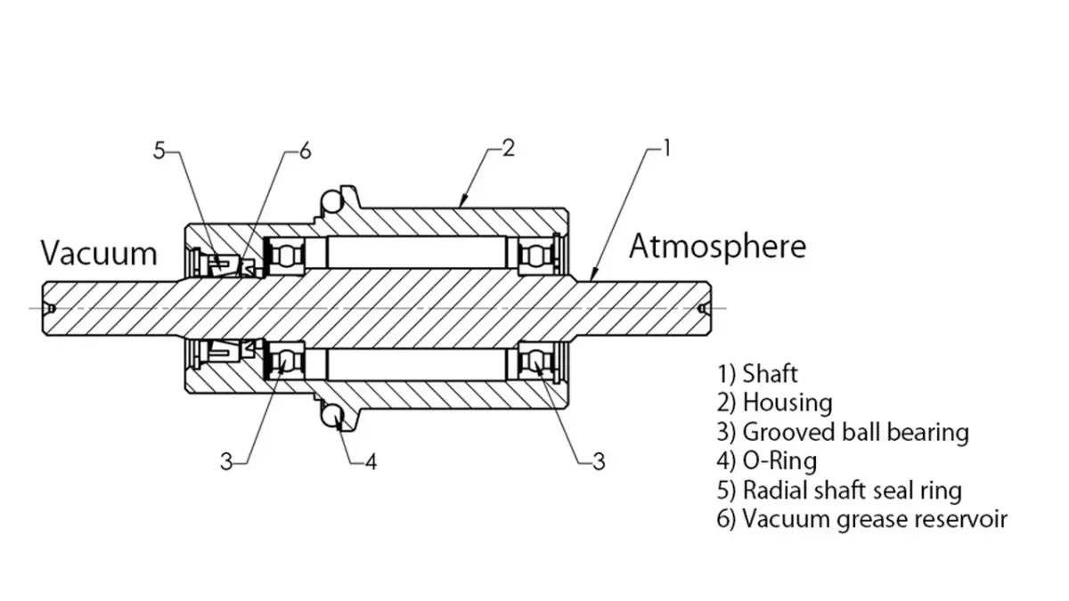
For vacuum-suitable seals subjected to dynamic stress, special elastomer seals are used, which are often made of the FKM (fluoroelastomer) material. The adjustment of the limiting size between housing, seal and actuator shaft must be done carefully, the same goes for the design and implementation of surface finishes.

For frequent movements and for the increase of the sealing effect, elastomer seals must be lubricated on the moving contact points, which reduces friction, prevents premature wear and evens out small irregularities on the surfaces. When selecting a suitable vacuum grease or oil for maximum operating and bakeout temperature, their properties must be considered, particularly the vapor pressure.

Elastomer-sealed feedthroughs are only partially bakeable. In addition, it must be examined whether components of the grease or low amounts of hydrocarbons are compatible with the application. In consideration of these limitations, elastomer-sealed mechanical feedthroughs represent an economical alternative to more expensive devices with functional principles, if highest demands on vacuum quality are not priority.
An advantage of the continuous actuator shaft is the direct connection of the vacuum-side application with the drive on the atmosphere side. There is no play or load-dependent positioning error. Depending on the dimensioning and mounting of the actuator shaft, large loads can be moved as well.

With elastomer-sealed feedthroughs, rotational and linear motion and simultaneous rotation/linear motion can be implemented.

3.7.1.5 Rotation via sliding gaskets with pumped interspaces

The only way to manufacture a manipulator with a free passage and flanges that are freely rotatable to one another, is by using sliding gaskets. Since a sliding gasket alone does not provide a UHV-tight separation, multiple are wired in series and the interspaces are evacuated. Generally three special PTFE sliding gaskets are installed in series. For the first interspace one backing pump is sufficient. If UHV conditions should prevail in the interior, an additional interstage pumping is required, to which a high vacuum pump will be connected.

3.7.2 Accuracy, repeatable precision and resolution

Manipulators and mechanical feedthroughs have many different tasks. They range from continuous linear and rotational movements with specified speeds up to precise positioning tasks. Transport samples for analysis, move series products between process chambers or position measuring heads at their measuring point – such tasks often require only position accuracies of 0.1 to 1 mm. Other positioning processes require the most accurate repeatable precision of only a few micrometers or for tasks such as scans, the finest resolutions of 1 µm.

In order to be able to correctly identify requirements for the selection of a manipulator or a mechanical feedthrough, it is important to understand the following definitions, as well as, the equipment's properties and sources of errors.

The accuracy (precision) describes the deviation between the desired position and the actual position reached. Starting from one position, manually read from a scale or driven by a motor, ending at a position determined by a defined number of scale movements or motor steps.

Therefore the accuracy is determined by a variety of factors. Without claiming to be complete, here are some aspects that need to be considered frequently: How exact is the reading of the scale? How exact can the wheel be moved? How great is the division of the motor steps? Does the movement follow the motor step exactly? Furthermore, the properties of the guide and drive components are critical for accuracy: How big is the pitch error and the play of a spindle drive? How great is the deviation from the ideal leader of a linear guidance? Furthermore, attachments or air pressure of external loads cause deformations in the drive and guiding unit. If manipulators do not ensure adequate stability, the movable flange tilts during evacuation towards the connection flange.

The repeatable precision describes the deviation, with which a certain position can be achieved again. It is better or equals the precision, since not all errors are recorded. For example, unlike the play of components, the spindle-pitch error or leader deviation have no impact.

The resolution describes the smallest possible increment of movement. Pitch errors or guidance accuracy have also no impact. The readability of the scale or the smallest increment of the motor are crucial here. The requirement for this is, that the guide and drive unit follow the specifications. If, for example, due to the elasticity of the components and the difference between static and dynamic friction, it comes to a release among the sliding friction partners (stick-slip effect), such effects can determine the resolution. Recirculating ball systems are free from such effects and for demanding positioning tasks they are preferred over a slide unit.

3.7.3 Technical equipment and characteristics

Manipulators and mechanical feedthroughs can be mechanically designed either simple or sophisticated. Therefore is should be closely observed, whether the respective device meets the requirements regarding accuracy, durability and maintenance and if an ergonomic operability can be ensured.

3.7.3.1 Design features of a Z-axis precision manipulator

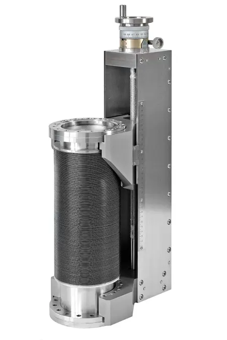
The use of recirculating ball systems with spindle drive and guidance have several significant advantages over conventional trapezoidal and metric screws drives or sliding guides. Due to their low friction, recirculating ball systems have a high efficiency and it is particularly favorable with large nominal diameters. Despite high external loads (such as the difference in pressure in an evacuated state), they allow for comfortable travel adjustment with a moderate operating force. The previously described stick-slip effect is not present, so that a very fine resolution is available and no breakaway torque will occur, which could make the operation more difficult and have particularly a negative impact on motor drives. Reduction gear that support motors, are not necessary here. Another advantage is the very low level of wear. In a clean environment that does not lead to contamination of the grease, the original lubrication, made of high-quality long-term high-temperature grease, will practically last indefinitely and no maintenance is required.
A guide body that is resistant to bending has a major effect on the precision. The choice of a stable U-shape made of stainless steel leads to greater stiffness with low material input and the associated weight. Inside the U-shape, the guide rail is screwed into the sturdy rear panel. Compared to free-running shaft guides, which cannot be supported, profile rails have a low-deformation structure that implements, even under heavy loads, a precise adjustment in compliance with all spatial axes, across the full travel range.

The bellows unit is typically designed for 10,000 cycles at full use of the travel. The exchangeability of the bellows ensures that manipulators with high quality guide and drive bodies can still be used.

3.7.3.2 Design features of an XY-axis precision manipulator

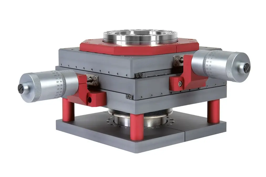
The design of an XY axis precision manipulator is also characterized by a very stable design, which represents a balance between weight, size and stability. Its weight-bearing basic structure is torsion resistant and made of an aluminum alloy, its surface is anodized and thus durably protected.
Precision crossed roller bearing guides ensure for a long life with utmost precision. The two axes are manually powered through the micrometer screws with a large actuation drum. It ensures a simple, ergonomic setting with a very good readability of the scale and therefore leads to a high resolution.

A clearance around the bellows unit, allows for the assembly of a heating sleeve, so that it can be heated evenly. Again, the bellows unit is easily replaceable, so that it can be exchanged after the configured number of cycles have run through.