Please update your browser. It looks like you are using an old version of the Microsoft Edge browser. To get the best experience with the Pfeiffer website, please update your browser.

Contact Customer portal
Global
  • EN
  • DE
  • ZH
  • KO

3.4 Vacuum chambers

The heart of a vacuum system is the vacuum chamber, which is tailored to specific application. It encloses the application and reliably separates it from the outside or protects the surrounding from the processes inside. Irrespective of whether a fine vacuum is required for drying processes, a medium or high vacuum for plasma processes or ultra-high vacuum for surface studies: – The vacuum chamber must always mechanically bear the pressure difference from the atmosphere.

Vacuum vessel within the European Union are not subject to any specific guidelines upon which a design and calculation has be based on. They are not pressure equipment (Pressure Equipment Directive 2014/68/EU applies to components with an internal gauge pressure greater than 500 hPa) and they are not classified as machines according to the Machinery Directive 2006/42/EC. Nevertheless, they must be designed, calculated, manufactured in a safe and reliable way and tested prior to commissioning.
The calculation of wall thickness for cylindrical tubes, spherical bodies, flat floors or mold parts, such as dished ends can be done using the AD-2000 leaflets. The AD 2000 regulation was actually designed by the “pressure vessel working committee“ for the calculation of pressure vessels, but which also describes the load condition “external overpressure”. Here you will find, for example, equations for calculating the required wall thicknesses that include the “elastic buckling” or “plastic deformation” of cylindrical tubes.
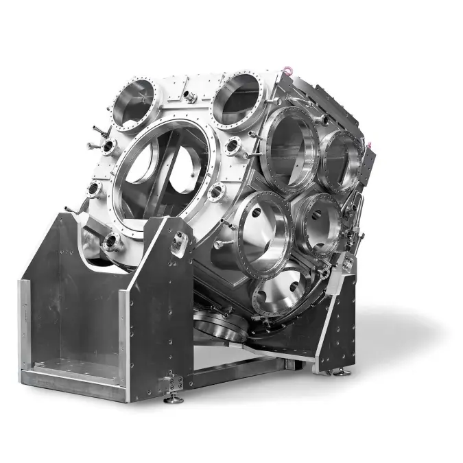
With rectangular chambers or similar designs, the deflection of the surfaces and the emerging tensions must be checked. If they are too high, the wall thickness must be increased or the areas must be reinforced, for example by additional welded ribs. For that, helpful programs that perform mechanical calculations using the finite element method (FEM) can be used to optimize the chamber design. In addition to the permissible mechanical stress, it is also necessary to check, whether under the load conditions “outside atmosphere, vacuum inside” the sealing surfaces remain flush with each other. If the sealing surfaces warp, leaks can occur that prevent the use of the chamber.
The basic shape of the chamber is often derived from the application. For the chamber body a cylindrical tube should be selected if possible, since it is the ideal for material input and stability. For smaller nominal diameters, a flat bottom can seal a tube side, larger diameters should be sealed by dished ends to limit the material input and the mass of the chamber. Example: Chamber diameter of 600 mm, requires a flat bottom, about three times the wall thickness as of a dished end. A main flange with fitting lid allows access to the chamber, a door hinge increases ease of use. Chamber feet on the outside ensure stability, eye bolts or hoisting shackles allow safe transport.

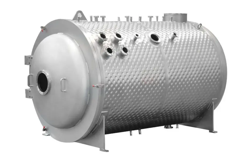
If the chamber is to be tempered or if internal heat sources lead to excessive heating of the chamber cover, a chamber cooling system must be provided. This can be achieved by welded cooling profiles or a pillow plate cooling for large areas (Figure 3.18) or even as a double-walled container.
Often, a chamber is designed in a dialog between user and designer according to an experiment or a process. An alternative to individually tailored chambers are standard vacuum chambers. These are preconfigured base bodies, complemented by freely selectable ports. They offer a faster and cheaper alternative to a completely customized vacuum chamber.

3.4.1 Processing - Surfaces

The topics “material selection” and “welding” were already covered in the previous chapters. The inner surfaces of vacuum chambers and components are a significant factor for achieving the operating pressure in the high vacuum and UHV. The processing must be carried out under the condition, to minimize the effective surface and to produce surfaces with small desorption rates.
The surfaces of vacuum chambers and components are often fine glass bead blasted after welding and mechanical processing. High-pressure glass beads with a defined diameter are blown onto the surface. Sealing surfaces cannot be blasted and so they are covered during blasting. The process seals the surface, it levels it microscopically, removes near-surface layers, such as discolorations and creates a decorative appearance. Surfaces to be blasted must be clean and free of grease, the grit media must be replaced regularly, especially when changing groups of materials, such as ferritic and austenitic stainless steels.
Brushing
is used for post-treatment of weld seams. The brushes used must be made of stainless steel and must not be contaminated by other materials, so that no foreign matter is introduced into the surface. The same goes for polishing. Polish or abrasion may not be added to the surface and/or must then be removed completely. The effective surface area must not be increased by microscopic roughening.
Pickling
is an effective method for cleaning the surface. Impurities and about a 1 to 2 µm thick layer are dissolved. Relevant pickling parameters such as the concentration of the stain, the temperature or the pickling time must be strictly observed to avoid overpickling. After pickling, it must be rinsed intensively to remove all remnants of the pickling liquid. The surface roughness is changed only insignificantly by the pickling process.
Electro-polishing
is the selective anodic dissolution of the metal into an electrolyte by using a DC power supply. In this case, typically 12 to 15 µm are removed from the surface to produce a crystalline pure surface. In order for the surface to be evenly removed, an electrode suited for the component must be manufactured frequently. This makes the process complex. In addition, the CF sealing surfaces must be covered, as the electric field strength is locally increased as the edges, resulting in an increased removal of material. Among UHV users, the process is disputed. The inclusion of hydrogen into the surface or through the electrolyte remnants on the surfaces are discussed. As with pickling, after the electro-polishing the components must be thoroughly rinsed. In addition, a leak test should be performed afterwards, as material is removed in the area of the weld seams. Depending on the previous condition, electro-polishing can cut the surface roughness by half.

3.4.2 Processing - Cleaning

Clean surfaces are a prerequisite in vacuum technology. All impurities must be removed from the surfaces, so they do not desorb under vacuum conditions and produce gas loads or deposit on components.
Initially a pre-treatment is required, for example, with a high pressure cleaner, to remove coarse dirt. Subsequently, the components will be cleaned in a multi-chamber ultrasonic bath. The first cleaning is under ultrasonic conditions with the addition of special cleaners, which clean and degrease the surfaces. Contaminations are coated with surfactants, lifted from the surface and bound in the cleaning bath. The pH of the cleaning bath must be adjusted to the chamber material. In other baths, the detergent is completely removed, by pre- rinsing followed by thorough rinsing with hot, deionized water. And quickly after that, drying must be done in hot, dust-free and hydrocarbon-free air. Large chambers are cleaned with steam or high-pressure cleaners with the addition of special cleaning agents. After that, it must be washed again several times with hot deionized water, quickly followed by a drying in hot air.
After cleaning, the vacuum-side surfaces must only be touched with clean, lint-free gloves. The packaging used is PE plastic films, and sealing surfaces and knife edge profiles are protected with PE caps.
The surface of cleaned components still represents an outgassing source. Specifically adsorbed water molecules and traces of hydrocarbons from storage in air are the biggest sources of residual gas sources in UHV. In order to effectively remove these from the surfaces, UHV chambers are heated. Under continuous evacuation at a pressure less than 1 · 10-6 hPa, the components are typically heated to temperatures of 150°C to 300°C for about 48 hours.
Foreign atoms bonded to the surfaces through physisorption or chemisorption obtain thermal energy through these processes, with which they can dissolve the bond and become released from the surface. The molecules released from the surface must be removed from the system by the vacuum pump. After cooling, a final pressure is obtained that has been reduced by several orders of magnitude. If the chamber is vented, the surfaces are once more become with molecules. Using dry nitrogen as the flood gas and brief exposure times to a dry atmosphere cannot completely prevent water buildup on the surfaces, only reduce it. In order to attain the final pressure within a tolerable pump-down time, smaller than 1 · 10-8 hPa, another bakeout is inevitable.