Please update your browser. It looks like you are using an old version of the Microsoft Edge browser. To get the best experience with the Pfeiffer website, please update your browser.

Contact Customer portal
Global
  • EN
  • DE
  • ZH
  • KO

3.6 Valves

Valves in vacuum systems can also be subject to special requirements, in addition to the general technical requirements for shut-off elements that are typical of vacuum technology and have to be taken into consideration in engineering the products.
The minimum displaced ultimate pressure and the high flow resistance of components in the molecular flow range must be taken into consideration in configuring and selecting vacuum valves. In addition, minimum leakage rates are required for the valve housing and valve seat. Vacuum-side lubricants for the moving parts in the valves must be suitable for the required pressure and temperature ranges, or avoided entirely, if possible, in high or ultra high vacuum. Minimum dead volumes and high conductivities are important, particularly in the molecular flow range.
The feedthrough for mechanical actuation elements must be designed in such a manner as to satisfy requirements with respect to tightness, as well as the pressure and temperature ranges. Depending on the quality, elastomer sealed feedthroughs (e.g. shaft seals) can be used for lower vacuum requirements in the pressure range greater than 1 · 10-4 hPa. While membran or spring bellows are used for pressure ranges of less than 1 · 10-4 hPa. In addition, valves sealed with a metal bellows can be baked out if appropriately engineered. Valves with elastomer sealed housing, plate or flangs are used for pressures of up to 1 · 10-8 hPa. The installation is generally done in a way that the atmospheric pressure is on the valve plate, in closed position, and thus increases the closing force.
All-metal valves, in which all seals are made of metal, are suitable for UHV applications and higher bake-out temperatures, however they usually require higher closing forces to seal. Soft metals (copper or special alloys) are used as sealing materials. In addition to higher closing forces, shorter seal service life must also be expected.
There are a variety of different types of valves for the various applications in the field of vacuum technology; these valves are named on the basis of their design or function.
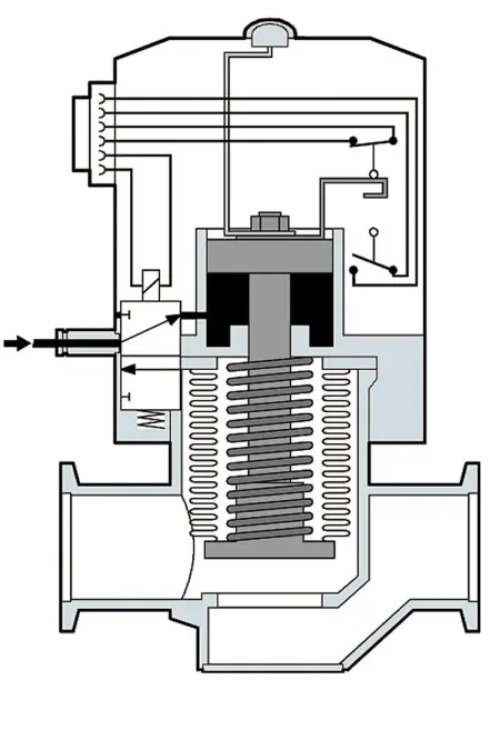
3.6.1 Valve control

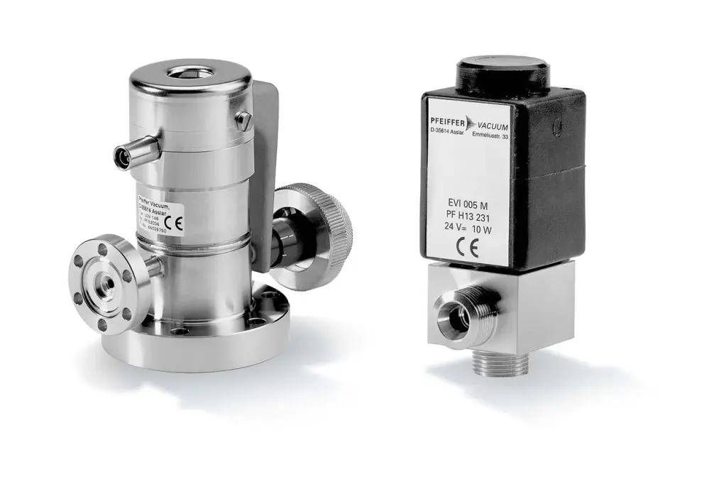
There are various ways in which valves can be actuated. Valves with small nominal diameters can be opened electromagnetically by electromagnets resp. coils. They generally close with spring force. For larger valves, the required coils are quite large and produce a lot of heat. After the opening of the solenoid current, the holding current can be reduced by the built-in control electronics to prevent overheating of the drive. Nevertheless, valves larger than dimensions DN 40 are rarely powered electromagnetically.
With a pneumatically operated valve, air pressure is used for actuation. The required control pressure is often in the range 0.4 to 0.8 MPa. A pneumatic cylinder transmits its movement to the valve plate. If a direction is operated by compressed air and the opposite direction reset with a spring, the drive is called “single acting pneumatic”. If compressed air is required for both directions, it is called “double acting pneumatic”. If there is an electromagnetic control valve for the inlet and outlet of the compressed air directly on the pneumatic drive head, there is an electro-pneumatic drive. Here, air pressure must applied and must be controlled by switching the control valve with its control voltage (often 24 V DC). For the regular pneumatic drive, an electromagnetic valve is also generally used for controlling the compressed air. But it is, for example, located in the cabinet or if many valves are connected, it is on a so-called valve terminal that houses the control valves. Should the control fail, it is often advantageous when the valves with return springs fall in a defined valve position. A distinction is made between the designs “normally closed” and “normally open“, where the standard is the closed position. In addition to that, valves can be operated by electric motors. Intermediate positions are also possible if the valve design permits.
Most valves have and “open / close” optical position indicator, which indicates the valve position. For automated processes, it is useful or even necessary to get feedback about the actual valve position, which is independent of the switching state. For that purpose, valves are equipped with valve position indicators that directly indicate the position of the valve plate. It indicates malfunctions, such as a failure of the compressed air or malfunction of the control valve.

3.6.2 Angle valves

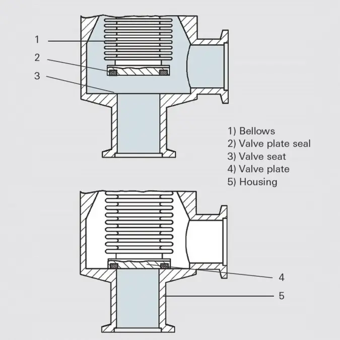
Angle valves are characterized by a high tightness, they are robust, suitable for industrial applications and resistant to dirt. The inlet and outlet flange are orthogonally aligned to one another on the aluminum or stainless steel housing. Figure 3.21 shows the design of a bellows-sealed angle valve. A trapezoidal or O-ring-shaped elastomer seal is located on the valve plate. The valve plate is forced against the valve seat to close the valve. Since the mechanical activation elements are located outside the vacuum range, they can be lubricated without any problem. Angle valves are available with all common flange types and are available in hand-operated, pneumatic, electro-pneumatic and solenoid actuated designs.
For UHV applications there are hermetically sealed valve housing and valve seat seals made of FKM or copper (all-metal designs).

3.6.3 Inline and diaphragm valves

Inline valves are basically of the same design as the above described angle valves. Except their inlet and outlet is located in an axis. Due to their design, the flow resistance of inline valves is usually higher than that of comparable angle valves.
Valves with smaller nominal diameters are available as diaphragm valves. The diaphragm seals the seat internally and externally.

3.6.4 Gate valves

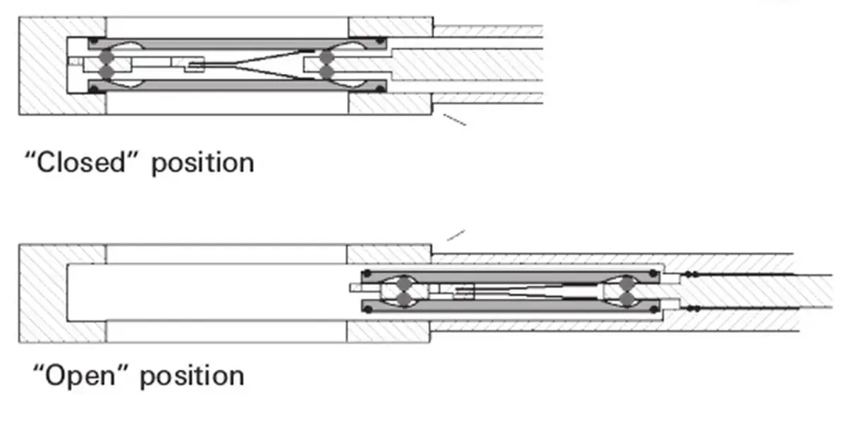
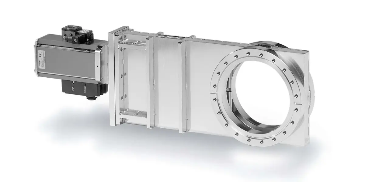
While the above described valves only partially release the nominal cross-section, gate valves offer a free passage in an open position. Together with their low installation height, it leads to high conductance and with that the required minimal performance losses during the use of high vacuum pumps.
Valve plates, usually of dual design, move back and forth to open and close these valves. In the closed position, both elements are forced apart and against the sealing surfaces by means of balls. Depending upon the direction of movement of the valve gate, a distinction is made between rebound valves, shuttle valves and rotary vane valves. While most gate valves can seal against a differential pressure of 0.1 MPa on the valve plate due to their special design, they can only open in the presence of a low differential pressure on the valve plate.

3.6.5 Butterfly and ball valves

The seal of a butterfly valve is mounted on the circumferences of the valve plate. The plate revolves around an axis, which runs transversely through the circular valve housing. The valve plate remains in the valve opening. The valve has a short design and a low flow resistance, as the gate releases almost the entire cross section.
Ball valves are extremely robust valves with free passage and vacuums to about 1 · 10-5 hPa. A ball with a hole through it is rotatably supported and sealed on both sides by means of universal ball joints (usually made of PTFE), which also have holes through them. When the hole is in the direction of the flow, the entire cross section is released. It should be noted that ball valves contain an enclosed volume when closed.
In the 3-way design, the ball bore is in the form of an “L” or “T”. Due to the size of the bore, the three ports may overlap when switching.

3.6.6 Gas dosing valves and gas control valves

Gas dosing valves are used for the inlet of defined gas flows into a vacuum system, for example, to maintain or set a certain pressure. They often work according to the principle of a needle valve. By turning a spindle, a gap is released and this opening and length provide the flow conductance. The gas flow is dependent on the spindle revolutions and is represented as a characteristic curve. The valve position can be read from a scale and set reproducibly.
Gas control valves are motor-controllable dosing or proportional valves, where the size of the valve opening continuously increases with the applied coil current, all the way up to the maximum opening. The volume flow associated with the coil current is illustrated in the characteristic curve. Control valves are operated by control units or are directly controlled by external controllers. They are used in automated processes for pressure or flow control.
For very low flow rates under UHV conditions, e. g. for mass spectrometer applications, there are bakeable all-metal gas dosing and gas control valves that seal with a ceramic plate against a metal seat.