-
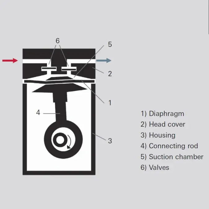
Figure 4.5: Operating principle of a diaphragm vacuum pump

4.3.2 Application
Their hydrocarbon-free suction chambers make diaphragm pumps particularly well suited as dry backing pumps for turbomolecular pumps with a Holweck stage. Even two-stage diaphragm pumps that can reach an ultimate pressure of approximately 5 hPa. This is sufficient for backing of pumps for Holweck turbopumps. The clean vacuum is particularly useful for analytical and R&D applications. Diaphragm pumps, too, do not displace water vapor without gas ballast. Even the low volumes of water vapor that desorb from the walls of high vacuum equipment can allow the ultimate pressure of a diaphragm pump to increase dramatically. However, some diaphragm pumps are equipped with a gas ballast valve that operates in accordance with a patented process. For this purpose, gas is admitted into the connection channel between the first and second stages of two-stage diaphragm pumps, and this is connected with the suction chamber of the first stage via a small hole.Diaphragm Pumps | |||
|---|---|---|---|
Model | Pumping speed | Ultimate pressure | Applications |
MVP 003-2 | 0.25 m³ · h-1 | ≤ 7.0 hPa | Small turbopump pumping stations (ideal with HiPace 10 and HiPace 80), mobile analysis devices, MiniTest helium leak detector regeneration |
MVP 006-4 | 0.25 m³ · h-1 | ≤ 2.0 hPa | Small turbopump pumping stations (ideal with HiPace 10 and HiPace 80), mobile analysis devices |
MVP 015-2 | 0.5 m³ · h-1 | ≤ 3.5 hPa | Turbopump pumping stations, leak detectors, research laboratories, analytical and chemical applications |
MVP 015-4 | 0.5 m³ · h-1 | ≤ 0.5 hPa | |
MVP 030-3 | 1.8 m³ · h-1 | ≤ 2.5 hPa | |
MVP 040-2 | 2.3 m³ · h-1 | ≤ 4.0 hPa | |
MVP 070-3 | 3.8 m³ · h-1 | ≤ 1.0 hPa | |
MVP 070-3 C | 3.4 m³ · h-1 | ≤ 1.5 hPa | Corrosive gas applications requiring a hydrocarbon-free vacuum |
Table 4.12: Diaphragm pump performance data
If greater volumes of moisture accumulate and diaphragm pumps without gas ballast are used, suitable separators or cooling traps must be connected upstream to prevent significant condensate formation in the pump. However, the ultimate pressure will nevertheless increase.
4.3.3 Portfolio overview
Diaphragm pumps from Pfeiffer Vacuum differ in terms of their ultimate pressure, pumping speed and their suitability for pumping corrosive gases. The pumping speeds of the pumps are between 3 and 160 l · min-1 (0.25 to 9.6 m3· h-1). Ultimate pressures of less than 4 hPa for two-stage pumps and less than 0.5 hPa for four-stage pumps can be attained. Their pumping speed and the attainable final pressure depend on the mains frequency.Corrosive gas pump models with coated diaphragms and corrosion-resistant housings are available for pumping corrosive gases.
The designations for the pumps are selected in such a manner as to indicate the pumping speed in l · min-1 and the number of pumping stages. Corrosive gas pumps have the letter C as a suffix to the model designation.
4.3.4 Accessories
The following accessories are available for diaphragm pumps:- Screw-in flanges and flange adapters
- Purge gas connection
- Fore-vacuum relay boxes
- Power supply packs for wall or standard rail mounting
- Cable for connection to turbopump drive