Please update your browser. It looks like you are using an old version of the Microsoft Edge browser. To get the best experience with the Pfeiffer website, please update your browser.

Contact Customer portal
Global
  • EN
  • DE
  • ZH
  • KO

4.1 Vacuum pumps – working principles and properties

4.1.1 Classification of vacuum pumps

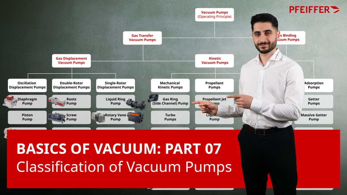
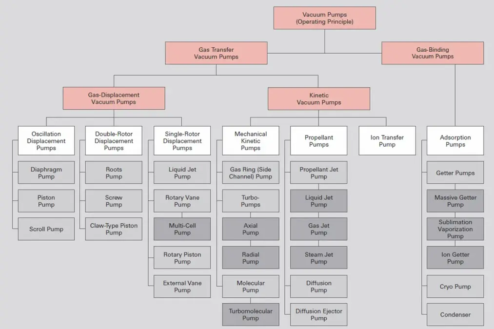
Vacuum pumps are categorized as gas transfer pumps and gas binding or capture pumps. While gas-displacement vacuum pumps can be used without limitation, gas-binding vacuum pumps have a limited gas absorption capacity and must be regenerated at certain process-dependent intervals.
Gas-displacement pumps, which are also referred to as gas transfer pumps, are classified either as positive displacement pumps or kinetic vacuum pumps. Positive displacement pumps displace gas from sealed areas to the atmosphere or to a downstream pump stage. Kinetic pumps displace gas by accelerating it in the pumping direction, either via a mechanical drive system or through a directed vapor stream that is condensed at the end of the pumping section. Gas-binding vacuum pumps either bind the gas to an especially active substrate through gettering or condense the gas at a suitable temperature. Chemisorption is performed technically by a pump type known as getter pumps which constantly generate pure getter surfaces through vaporization and/or sublimation or sputtering. If the gas particles to be bound are ionized in an ion getter pump before interacting with a getter surface, they can at the same time clean the getter surface by sputtering and be buried by sputtered material. Non evaporable getters (NEG) consist of highly reactive alloys, mainly of zirconium or titanium, and have a very large specific surface. Gases can penetrate into deeper layers of the getter material through micropores and be bound there into stable chemical compounds.
4.1.2 Pumping speed and throughput

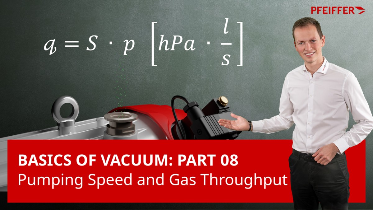
The pumping speed
(Formula 1-17) is the mean volume flow through the cross section of the inlet port of a vacuum pump. In diagrams the volumetric flow rate or pumping speed is displayed on the Y axis versus the inlet pressure on the X axis. The maximum pumping speed which a pump can achieve due to its geometry is referred to as its rated pumping speed. Determination of the pumping speed is described in basic standard ISO 21360-1: 2012. Pumping speed is indicated in m3 · s-1. The units of m³ · h-1, l · s-1 and l · min-1 are also customary.
The throughput
(Formula 1-16) denotes the gas throughput in a vacuum pump as a function of inlet pressure. It is expressed in Pa · m3 · s-1 or hPa · l · s-1 = mbar · l · s-1. In the case of pumping stations that consist of gas-displacement pumps, all pumps connected in series have an identical throughput.

4.1.3 Ultimate pressure and base pressure

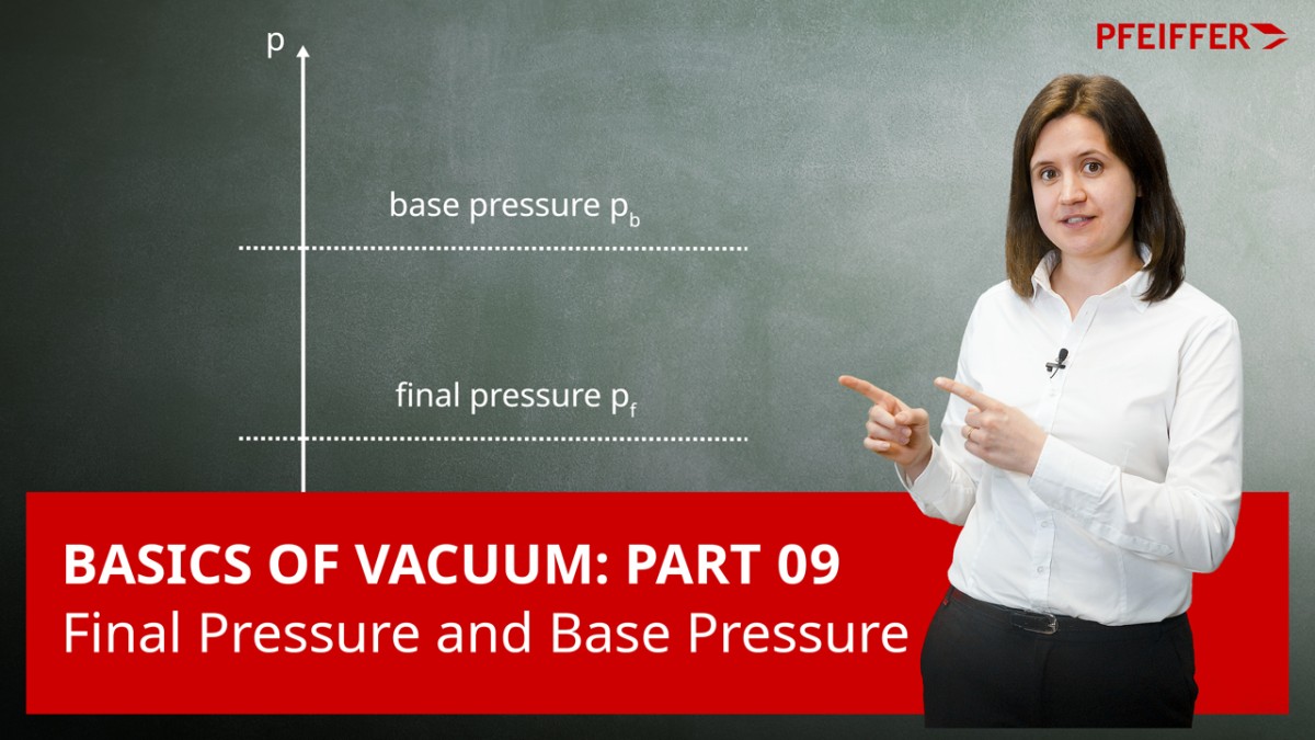
Ultimate pressure pe is the lowest pressure that is asymptotically approached by the pressure of a blank-flanged vacuum pump under defined conditions without gas inlet. If a pump is operated at ultimate pressure, the usable pumping speed will be zero, as only its own backflow losses will be displaced. Ultimate pressure is a theoretical value. Today, base pressure is specified instead of ultimate pressure. The conditions for achieving base pressure are specified in standard ISO 21360-1:2012. As the base pressure must be attained within a specified period of time, it is usually higher than the ultimate pressure.

4.1.4 Compression ratio

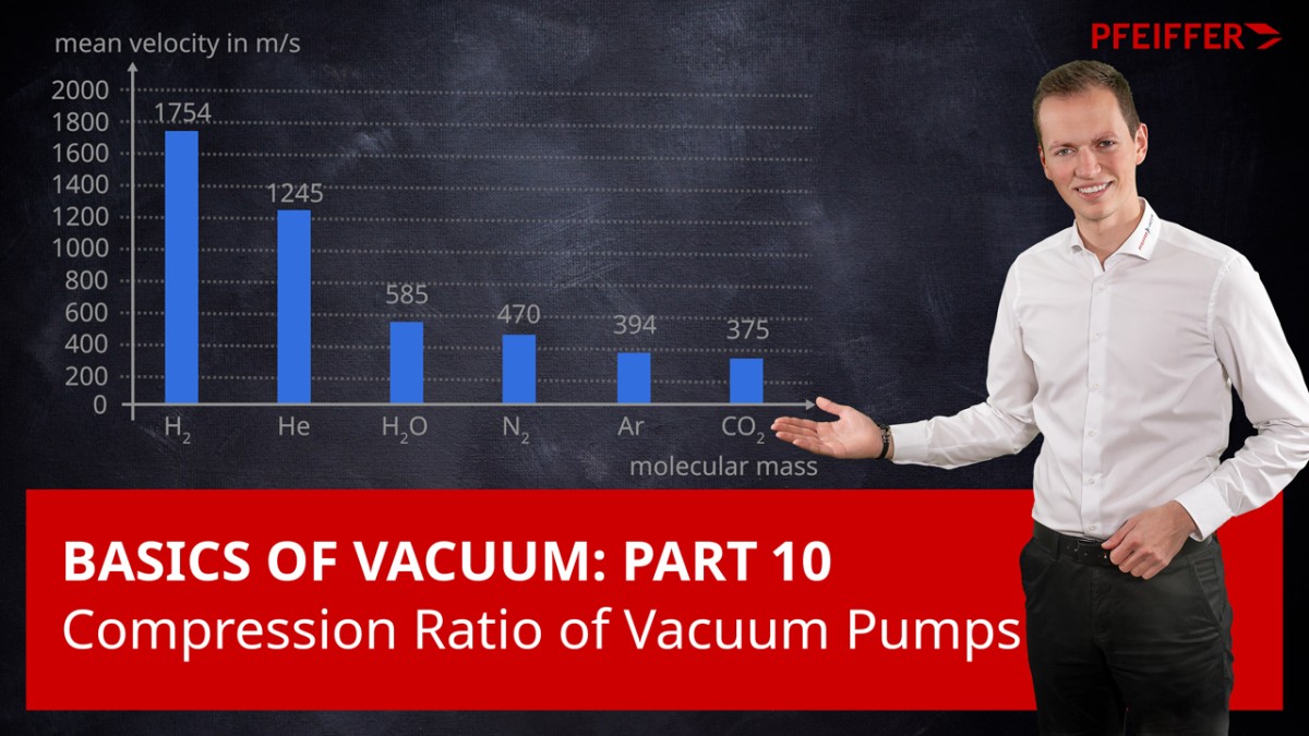
In the case of blank-flanged inlet ports, the compression ratio (called K_0 due to zero delivery) is measured through gas intake on the outlet side provided that this is not expelled against constant atmospheric pressure.

4.1.5 Pumping speed of pumping stages connected in series

Let us consider a vacuum pump having a pumping speed S0 and a compression ratio K0. The pump has backflow losses through gaps with conductivity CR. Let inlet pressure be pinlet and discharge pressure poutlet. An additional pump having a pumping speed Sb is connected on the outlet side. This could be a Roots pumping station or a turbopumping station, for instance.
The overall pumping station with a pumping speed S delivers the gas quantity
For backflow conductivity CR, the following applies where C_{R} << S_0
and for the actual compression ratio
Using the above formulas, it therefore follows that the pumping speed S of a two-stage pumping station will be
This formula can also be used as the recursion formula for multiple pumping stages that are connected in series by starting with the pumping speed Sb of the last stage and inserting the K0 and S0 of the preceding stage.

4.1.6 Gas ballast

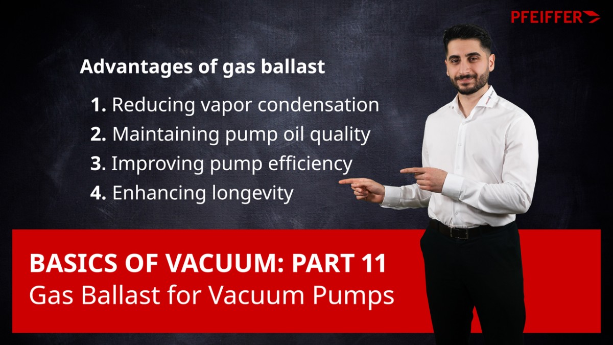
Means through which air or another non-condensing gas is admitted into a vacuum pump are referred to as gas ballast. If the pump is displacing vapor that would condense in the pump at the corresponding temperatures without gas ballast, the gas ballast enables the outlet valve to open before the vapor condenses, and the vapor is discharged together with the ballast gas. Both atmospheric air as well as selected inert or process gases are used as ballast gas. The use of gas ballast slightly increases the attainable base pressure of a vacuum pump. Consequently, for gas ballast vacuum pumps the base pressure is specified both with and without gas ballast.

4.1.7 Water vapor tolerance / water vapor capacity

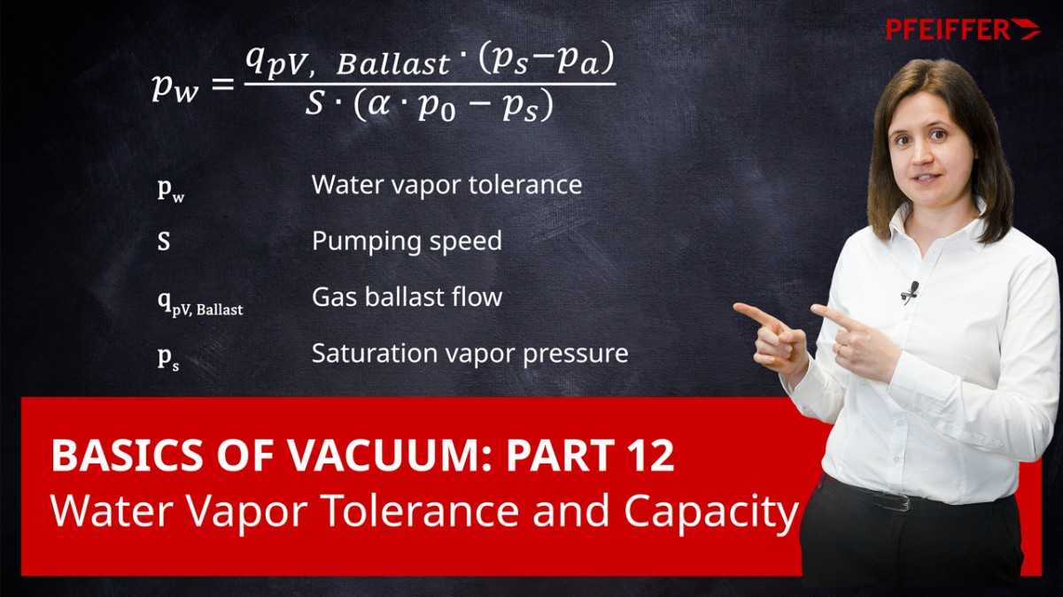
Water vapor tolerance pw is the maximum water vapor pressure with which a vacuum pump can continuously intake and displace pure water vapor under normal ambient conditions (20 °C, p0 = 1,013 hPa). It can be calculated from the pumping speed, gas ballast flow, relative humidity and saturation vapor pressure at a given pump temperature.
  • pW Water vapor tolerance
  • qpV Ballast Gas ballast flow
  • S Pumping speed of pump
  • pS Saturation vapor pressure of water vapor at exhaust gas temperature
  • pa Partial pressure of water vapor in the air
  • p0 Atmospheric pressure
  • α Correction factor, dimensionless

The correction factor takes into account the fact that a higher pressure than atmospheric pressure is required to open the outlet valve. In our example α can be assumed as 1.1.
The water vapor tolerance has the dimension of a pressure and is expressed in hPa.
DIN 28426 describes the use of an indirect process to determine water vapor tolerance. The water vapor tolerance increases as the exhaust temperature of the pump rises and gas ballast flow qpV,Ballast increases. It decreases at higher ambient pressure.
Without gas ballast, a vacuum pump having an outlet temperature of less than 100°C would not be capable of displacing even small amounts of pure water vapor. If water vapor is nevertheless pumped without gas ballast, the condensate will dissolve in the pump oil. As a result, the base pressure will rise and the condensate could cause corrosion damage.
The water vapor capacity is the maximum volume of water that a vacuum pump can continuously intake and displace in the form of water vapor under the ambient conditions of 20 °C and 1,013 hPa.
  • qm,water 수증기 용량
  • M 물의 몰 질량
  • R 일반 기체 상수
  • T 절대 온도
The water vapor capacity is expressed in g · h-1. It is therefore a water vapor mass flow rate. The symbol cW (water vapor capacity) is commonly used to express this in formulas.

4.1.8 Sealing gas

When pumping corrosive process gas, there is a risk that the gas might attack parts of the pump. To counter this danger, sensitive parts must be protected by a continuous flow of inert gas. Pumps are therefore fitted with a special gas inlet system through which gas flows into the pumping system at defined locations. In turbo-molecular pumps, it is principally the bearings and the motor compartment which require protection. The intake of sealing gas in the motor compartment protects against chemical reactions by aggressive gases with corosion-sensitive components of the lubricant or the bearings as well as preventing dust and particles entering the lubricant reservoir and mixing with the lubricant. The use of sealing gas to protect the motor and prevent particles from entering and causing contact between the shaft and the emergency bearings, for instance, is also recommended for lubricant-free turbopumps.
In addition to sealing gas for the bearings, process-capable dry backing pumps also have purge gas injected into individual pumping stages of the process pump. The process-dependent purge gas flow is adjusted using pressure regulators upstream of the calibrated nozzles or flow regulators (mass flow controllers, or MFC) and monitored by pressure sensors and switches.