Please update your browser. It looks like you are using an old version of the Microsoft Edge browser. To get the best experience with the Pfeiffer website, please update your browser.

Contact Customer portal
Global
  • EN
  • DE
  • ZH
  • KO

4.9 Turbomolecular pumps

4.9.1. Design / Operating principle

The turbomolecular pump was developed and patented at Pfeiffer Vacuum in 1958 by Dr. W. Becker. Turbomolecular pumps belong to the category of kinetic vacuum pumps. Their design is similar to that of a turbine. A multi-stage, turbine-like rotor with bladed disks rotates in a housing. The blades of a turbine or a compressor are referred to collectively as the blading. Interposed mirror-invertedly between the rotor disks are bladed stator disks having similar geometries.

Bearings

Mounting the shaft of a turbopump rotor by means of two ball bearings requires arrangement of both bearings on the fore-vacuum side due to the lubricants in the bearings. This results in a unilateral (cantilever) support of the rotor with its large mass.
Hybrid bearing support offers advantages in this regard with respect to rotor dynamics. Hybrid bearing designates the use of two bearing concepts in one single pump. In this case, an oil-lubricated ball bearing is mounted on the end of the shaft on the fore-vacuum side, and the high vacuum side is equipped with a maintenance-free and wear-free permanent magnetic bearing that centers the rotor radially. The oil for lubricating the fore-vacuum side bearing is contained in an operating fluid reservoir. A small dry safety bearing is arranged within the magnetic bearing stator. During normal operation, a journal rotates freely within this bearing. In the event of strong radial shocks, the safety bearing stabilizes the rotor and rotates only briefly. If the rotor is out of balance, the bearings on both ends of the shaft will generate significantly lower bearing-stressing vibration forces than in the case of a floating bearing. The magnetic bearing on the high vacuum side is totally insensitive to vibration. Only very small vibration forces are transferred to the housing as a result. Moreover, this eliminates the need for the larger of the two bearings in a cantilever concept, whose size limits rotational speed.
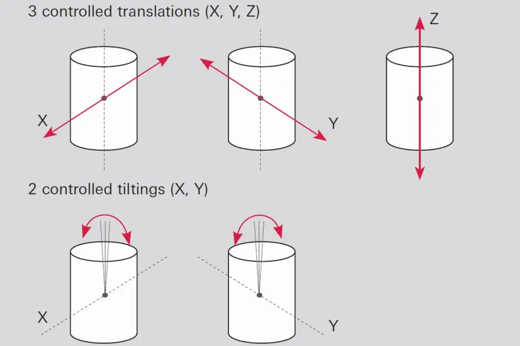
Large pumps from a flange diameter of 100 mm alternatively use bearings known as 5-axis magnetic bearings [24]. The rotor is levitated through digital electronic control via distance sensors and electromagnets. The degrees of freedom of the movement of a turborotor are continuously monitored and readjusted in real time. The absence of mechanical contact between the rotor and housing keeps the vibration generated by the pump low. The rotor revolves around its own axis of inertia. Any imbalance due to one-sided coating or erosion (such as in plasma etching) is counteracted within broad limits.
In addition to the absence of oil on the backing-vacuum side, freedom from wear and maintenance is another advantage. In the event of a power failure, the magnetic bearings are supplied with electricity through the rotational energy of the pump. This enables power failures to be easily bridged for several minutes. Should the power failure be of longer duration, the rotor will safely come to a stop at a very low speed through the use of an integrated safety bearing. During system malfunctions, the safety bearing shuts down the rotor to avoid any damage to the pump.
Motors / Drives

Brushless DC motors that afford rotational frequencies of up to 1,500 Hz (90,000 rpm) are used to drive the rotors. This enables the blade velocities that are necessary for pumping the gases.
Today, the drives are typically attached directly to the pumps. The power supply is with 24, 48 or 72 volt direct current, generated by external power supply packs or ones that are integrated in the electronic unit of the pump.

4.9.1.1 Turbomolecular pump operating principle

The pumping effect of an arrangement consisting of rotor and stator blades is based upon the transfer of impulses from the rapidly rotating blades to the gas molecules being pumped. Molecules that collide with the blades are adsorbed there and leave the blades again after a certain period of time. In this process, blade speed is added to the thermal molecular speed. To ensure that the speed component that is transferred by the blades is not lost due to collisions with other molecules, molecular flow must prevail in the pump, i. e. the mean free path must be greater than the blade spacing.
In the case of kinetic pumps, a counterpressure occurs when pumping gas; this causes a backflow. The pumping speed is denoted by S0. The volume flow rate decreases as pressure increases and reaches a value of 0 at the maximum compression ratio K0.

Compression ratio

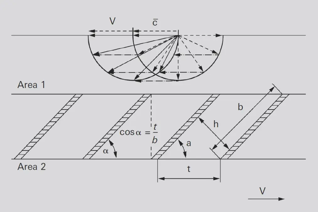
The compression ratio, which is denoted K0K0, can be estimated according to Gaede [25]. The following applies for a visually dense blade structure (Figure 4.22):
\bar{c} Mean molecule velocity[m · s1]
v Circumferential speed[m · s-1]
The geometric ratios are taken from Figure 4.22. The factor g is between 1 and 3 [26]. From the equation, it is evident that K0 increases exponentially with blade velocity vv as well as with √M because
Consequently, the compression ratio for nitrogen, for example, is significantly higher than for hydrogen.

Volume flow rate (pumping speed)

Pumping speed S0 is proportional to the inlet area A and the mean circumferential velocity of the blades v, i. e. rotational speed. Taking the blade angle α into account vields:
Taking into account both the entry conductance of the flange
as well as the optimal blade angle of 45°, produces the approximate effective pumping speed Seff of a turbopump for heavy gases (molecular weight > 20) in accordance with the following formula:
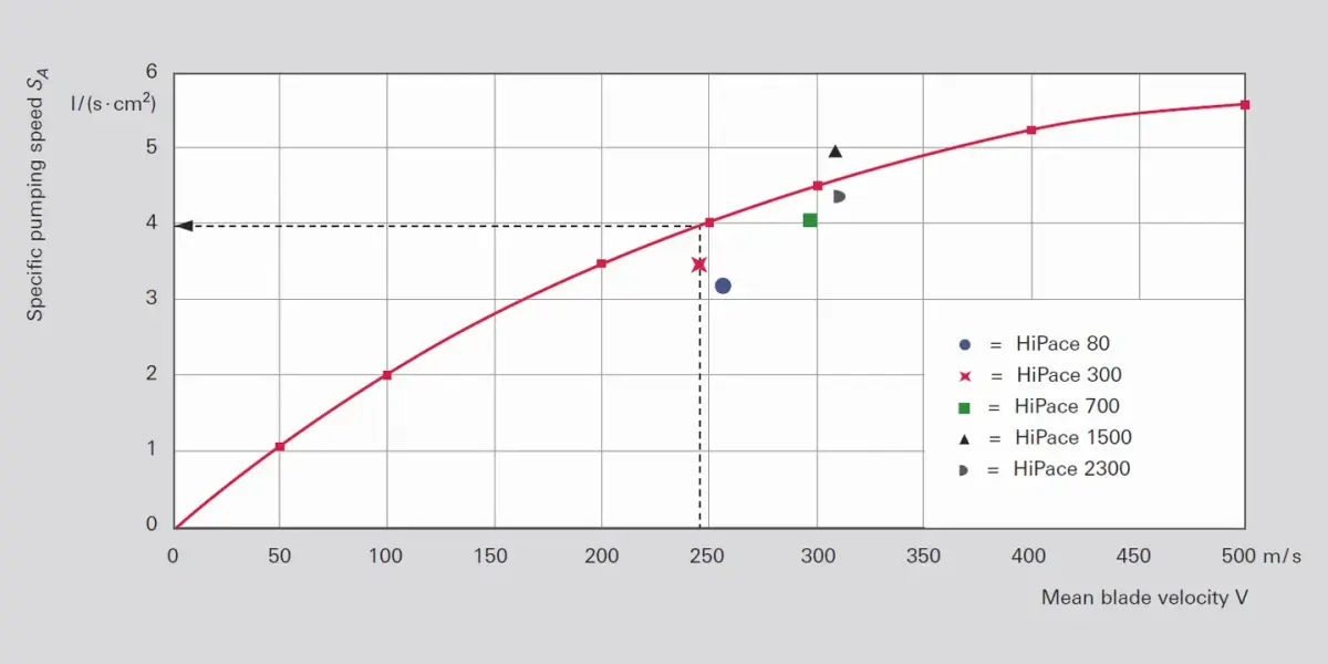
Dividing the effective pumping speed by the bladed entry surface of the uppermost disk and taking the area blocked by the blade thickness into consideration with factor df≈ 0.9, yields the specific pumping speed of a turbopump for nitrogen, for example (curve in Figure 4.23):
On the Y axis in Figure 4.23 the specific pumping speed is plotted in l · s-1 · cm-2 and the mean blade velocity v=\pi\cdot f\cdot(R_{a}+R_{i}) is plotted on the X axis. Moving up vertically from this point, the point of intersection with the curve shows the pump’s maximum specific pumping speed SA. Multiplying this value by the bladed surface area of the inlet disk: A=(R_{a}^2-R_{i}^2)\cdot\pi , obtains the pumping speed of the pump and enables it to be compared with the catalog information.
The points plotted in Figure 4.23 are determined by Pfeiffer Vacuum on the basis of the measured values of the indicated pumps. Points far above the plotted curve are physically not possible.
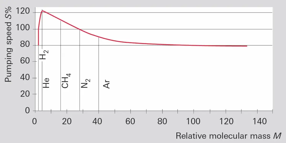
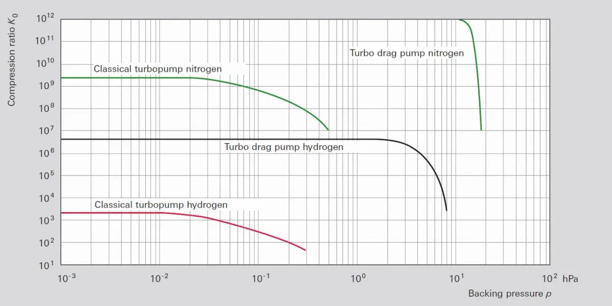
The pumping speeds thus determined still tell nothing about the values for light gases, e.g. for hydrogen. If a turbopump is designed for a low ultimate pressure, pump stages with various blade angles are used and the gradation is optimized for maximum pumping speeds for hydrogen. This produces pumps with sufficient compression ratios for both hydrogen (approximately 1,000) and nitrogen, which should be 109 due to the high partial pressure of nitrogen in the air. In the case of pure turbomolecular pumps, backing-vacuum pressures of approximately 10-2 mbar are required due to their molecular flow.

4.9.1.2 Holweck stage operating principle

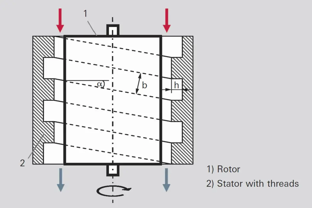
A Holweck stage (Figure 4.26) is a multi-stage Gaede type molecular pump having a helical pump channel. Due to the rotation of the rotor, gas molecules entering the pump channel receive a stimulus velocity in the direction of the channel. Backflow losses occur through gaps between the barriers that separate the Holweck channels from each other and the rotor. The gap widths must be kept small to minimize backflow. Cylindrical sleeves (1) that rotate about helical channels in the stator (2) are used as Holweck stages. Arranging stators both outside as well as inside the rotor enables two Holweck stages to be easily integrated within one and the same pump. This means that the displaced gas particles are transported outside the rotor through the stator channel and then inside the rotor through further stator channels until they are conveyed back up to the backing pump through a collecting channel. Some modern turbopumps have several of these ”pleated“ Holweck stages.
The pumping speed S0 of the Holweck stages is equal to:
Where bh is the channel cross section and v⋅cosα the velocity component in the channel direction.
The compression ratio increases exponentially as a function of channel length L and velocity v⋅cosα [4]:
The values yielded with this formula are not attained in real Holweck stages since backflow over the barrier from the neighboring channel dramatically reduces the compression ratio, and this influence is not taken into account in Formula 4-13.
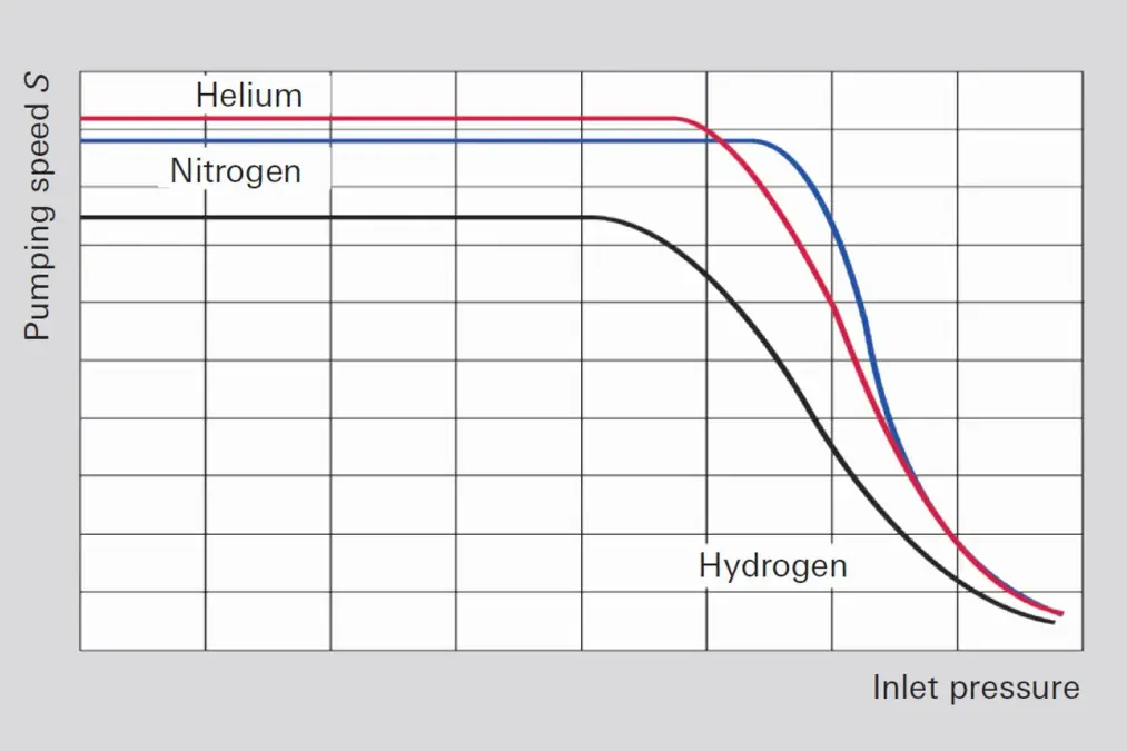
To set up a turbo pumping station with diaphragm pumps with a final pressure of between 0.5 and 5 hPa, turbopumps are today equipped with Holweck stages. These kinds of pumps are termed turbo drag pumps. Since only low pumping speeds are required to generate low base pressures due to the high pre-compression of the turbopump, the displacement channels and, in particular, both the channel height as well as the clearances to the rotors can be kept extremely small, thus still providing a molecular flow in the range of 1 hPa. At the same time, this increases the compression ratios for nitrogen by the required factor of 103. The shift of the compression ratio curves to higher pressure by approximately two powers of ten can be seen from Figure 4.27.
For turbopumps which are designed for high gas throughput, a compromise is made where the gas throughput, fore-vacuum compatibility and particle tolerance are concerned and the distance between the gaps in the Holweck stages is increased.

4.9.1.3 Turbopump performance data

Gas loads

that can be displaced with a turbomolecular pump increase proportionally to pressure in the range of constant volume flow rate. In the declining branch of the pumping speed curve the maximum displaced gas loads can continue to rise but they will reach thermal limits that depend on the size of the backing pump. The maximum permissible gas loads also depend on the pump temperature (cooling and/or heated pump) and the type of gas in question. Displacing heavy noble gases is problematic, because they generate a great deal of dissipated energy when they strike the rotor, and due to their low specific heat, only little of it can be dissipated to the housing.
Measurement of the rotor temperature by the manufacturer enables gas type-dependent process windows to be recommended for safely operating the turbopumps. The technical data for the turbopumps specify the maximum permissible gas loads at nominal rpms for hydrogen, helium, nitrogen, argon and CF4. A reduction in the rotation speed allows higher gas throughputs.
Pumps in the HiPace series with pumping speeds > 1,000 l · s-1 are equipped with rotor temperature monitoring and protect themselves from overheating.

Critical backing pressure

Critical backing pressure is taken to mean the maximum pressure on the backing-vacuum side of the turbomolecular pump at which the pump’s compression decreases. This value is determined as part of the measurements for determining the compression ratio in accordance with
ISO 21360-1:2012 by increasing the backing pressure without gas inlet on the intake side. In the technical data for turbomolecular pumps, the maximum critical backing pressure is always specified for nitrogen.

Base pressure, ultimate pressure, residual gas

In the case of vacuum pumps, a distinction is made between ultimate pressure and base pressure (see also Section 4.1.3). While the pump must reach base pressure pb within the prescribed time under the conditions specified in the measurement guidelines, the ultimate pressure pe can be significantly lower. In the HV range, base pressure is reached after 48 hours of bake-out under clean conditions and with a metallic seal. What is specified as the base pressure for pumps with aluminum housings is the pressure that is achieved without bake-out and with clean FKM seals.
Corrosive gas-version pumps have a higher desorption rate which can temporarily result in higher base pressures due to the coating on the rotor surface.
Dividing the backing pressure by the compression ratio yields the ultimate pressure.
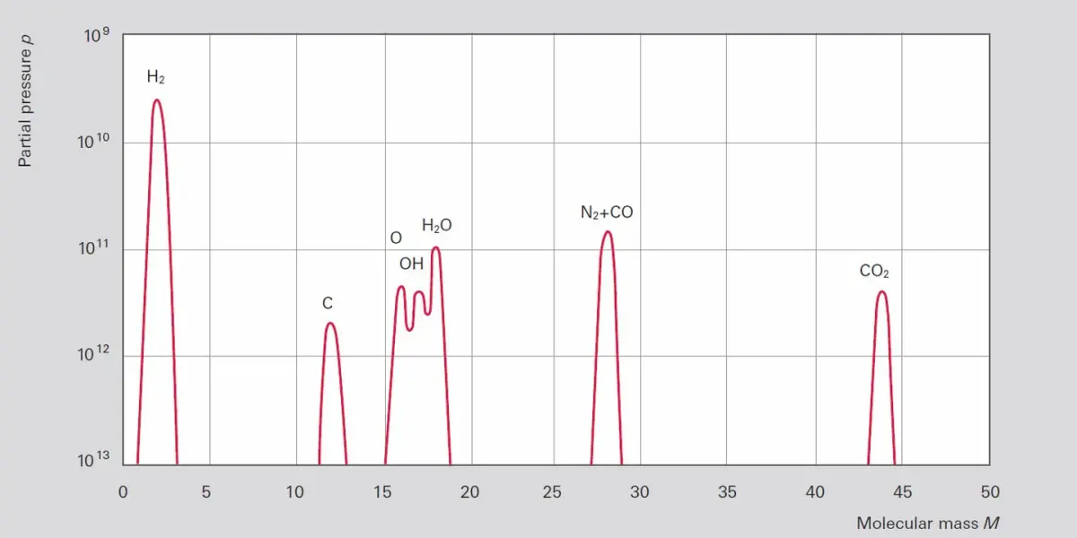
Whether ultimate pressure will be achieved will depend upon the size and cleanliness of both the equipment and the pump, as well as upon the bake-out conditions. After extreme bakeout (to over 300 °C) only H2, CO and CO2 will be found in the residual gas. These are gases that are dissolved in the metal of the vacuum chamber and continuously escape. A typical residual gas spectrum of clean, baked out equipment is shown in Figure 4.28.
In the backing pump used, the gas ballast should be switched on at regular intervals to prevent the accumulation of hydrogen in the fore-vacuum area. In many cases, the actual ultimate pressure will be a factor of the desorption conditions on the high vacuum side of the turbopump and its pumping speed, and not the compression ratios of the pumps.

4.9.2 Application

Turbopumps are suitable for generating clean vacuum in the range of 10-3 to 10-10 hPa. Thanks to their high compression ratio, they reliably keep oil from the inlet area of oil-sealed pumps away from the recipient. Models with stainless steel housings and CF flanges can be baked out. This makes these pumps ideally suited for research and development applications where ultra-high vacuum requires to be attained.
Turbopumps can be used for evacuating large vessels with rotary vane pumps as backing pumps. In the case of turbo drag pumps, two-stage diaphragm pumps will suffice as backing pumps; however due to their low pumping speed, it will take them a great deal of time to pump down larger vessels. The gas throughput of this pump combination will also be highly restricted by the diaphragm pump. However this combination is an extremely cost-effective solution for a dry pumping station. It is often used for differentially pumped mass spectrometers and other analytical or research and development applications. If higher pumping speeds are required in the backing pump area, we recommend using multi-stage Roots pumps from the ACP series or, for chemical vacuum processes in the semiconductor or solar industry, the process-capable backing pumps.
Pumping stations consisting of a backing pump and a turbopump do not require valves. Both pumps are switched on at the same time. As soon as the backing pump has reached the necessary fore-vacuum, the turbopump quickly accelerates to its nominal speed and quickly evacuates the vessel to a pressure of p < 10-4 hPa with its high pumping speed. Brief power failures can be bridged by the high rotational speed of the rotor. In the case of longer power failures, both the pump and the recipient can be vented automatically if the RPMs decline below a minimum speed.
The effects that play a role in evacuating vessels are described in Chapter 2. Dimensioning issues as well as the calculation of pump-down times are also described in that chapter.

Evacuating load lock chambers

Evacuating load-lock chambers definitely requires clean handling when transferring the workpieces to be treated in a vacuum process. If these items are channeled in from atmospheric pressure, the chamber should first be pre-evacuated via a bypass line. The running turbopump is then connected between the backing pump and the chamber via valves.

Analytical applications

In many cases, mass spectrometers are used in analyzers today. Fluids are often injected and evaporated in the inlet chamber of the vacuum system. Pressure is reduced in several stages, and the individual chambers are isolated from one another by orifices. Since each chamber must be pumped, the objective is to combine the gas flows via taps on the turbopump through the skillful combination of backing pumps and turbopumps. Specially modified turbopumps with taps are used for series applications. Besides the SplitFlow 50 described in Chapter 4.9.3, customer-specific solutions can be supplied.
Helium leak detectors, too, are equipped with turbopumps. In this case, the counter-flow principle is often used (see Chapter 7.2.1); i. e. a mass spectrometer is located on the high vacuum side of the pump. Due to the lower compression ratios of turbopumps for helium than for nitrogen or oxygen, the pump acts as a selective filter for helium.

Pumps with high gas loads in vacuum processes

The turbopump offers two advantages when pumping high gas loads for vacuum processes: It generates clean vacuum at the beginning of each process step, and can then pump down process gas without any harmful backflow. In the second step, the primary objective is to maintain a certain pressure at which the desired vacuum process should run. In this process, gas throughputs and working pressure will be determined by the application in question; i. e. a given volume flow rate will be pumped at a given gas throughput. Moreover, it should be possible to quickly achieve a clean intermediate vacuum when changing workpieces. Since these are conflicting requirements, a turbopump of sufficient size for the required gas throughput and the required intermediate vacuum must be selected. The process pressure will be regulated via an inlet valve (such as a butterfly valve). An example of how to dimension this kind of pumping station is shown in Chapter 2. The maximum permissible gas loads specified in the technical data should be taken to mean permissible continuous loads. This applies subject to the assurance of sufficient cooling in accordance with the specification and a backing pressure adjusted accordingly to below the maximum critical backing pressure.

Pumping corrosive and abrasive substances

When pumping corrosive gases, measures must be taken to protect the motor / bearing areas and the rotor, in particular, against corrosion. To do this, all surfaces that come into contact with corrosive gas are either provided with a coating or made from materials that can withstand attacks by these gases. A defined inert gas flow is admitted into the motor / bearing area in the fore-vacuum via a special sealing gas valve. From there, the gas flows through labyrinth seals to the fore-vacuum area, mixes with the corrosive gas and is pumped down by the backing pump together with the corrosive gas. In the case of pumps with bell-shaped rotors (e.g. the ATH M series), the sealing gas on the inner side of the Holweck stage can also act as convection cooling and increase the usable process window by reducing the temperature. Even in noncorrosive but dust-laden processes, sealing gas is an effective protection for the bearing and motor area.
The turbo-rotor blades can wear mechanically should dust accumulate; this could necessitate repairs and the replacement of the rotor. It should also be noted that deposits can be expected to form in the pump, which will shorten service intervals. In particular, it is necessary to ensure that deposits in the pump do not react to aggressive substances with moisture. Consequently, the pumps should be vented with dry inert gases only, and should be fitted with sealed fore-vacuum and high vacuum flanges when servicing is required. Turbopumps for these applications are either classic turbopumps without a Holweck stage, or turbopumps with a Holweck stage which would be a compromise between the critical backing pressure and the particle tolerance. Dust deposits in the Holweck stage resulting in blockage of the rotor can be reduced by increasing the gaps between the rotor and the stator in the Holweck stage. In an ATH M series turbopump, for instance, non-adherent dusts are primarily observed in the collecting channel near the fore-vacuum flange after long-term operation in a sputter application with particle content. The Holweck stage is still clean and the pump remains operational.

4.9.3 Portfolio overview

As a leading manufacturer of turbomolecular pumps, Pfeiffer Vacuum has mechanical-bearing and active magnetic-levitation ranges in its portfolio. Users will find models designed for high gas throughput or low ultimate pressure as well as pumps with minimum vibration or with additional taps (SplitFlow) in our portfolio.

4.9.3.1 Mechanical-bearing turbopumps

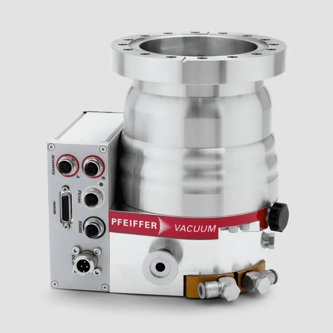
In the case of HiPace® turbopumps with oil-lubricated ball bearings on the fore-vacuum side and permanent-magnet bearings on the high vacuum side, a distinction is made between the following turbopump series:
  • HiPace® with ISO-K flanges: HiPace turbo drag pumps with Holweck stages for generating high vacuum for standard applications
  • HiPace® with CF flanges: HiPace turbo drag pumps with Holweck stages for generating ultra-high vacuum
  • HiPace® Plus: HiPace turbo drag pumps with Holweck stages with a reduced magnetic stray field and an extra low vibration level
  • HiPace® P: classic turbopumps for applications with a dust content
Table 4.21 contains the characteristics of standard pumps with hybrid bearings. All other series are modifications of these standard models and essentially have the same characteristics.
The base pressures of standard pumps with ISO-K flanges are: pb < 1 · 10-7 hPa. After baking out, pumps with CF flanges attain base pressures of pb < 5 · 10-10 hPa.

4.9.3.2 Active magnetic-levitation turbopumps

Table 4.22 contains the characteristics of turbopumps with active 5-axis magnetically levitated bearings.
These pumps, too, are available as:
  • HiPace® M with ISO-K or ISO-F flanges: HiPace turbo drag pumps with Holweck stages for generating high vacuum for standard applications
  • HiPace® M with CF flanges: HiPace turbo drag pumps with Holweck stages for generating ultra-high vacuum
  • ATP M: classic turbopumps without Holweck stages with a high compression ratio for light gases and a high particle tolerance
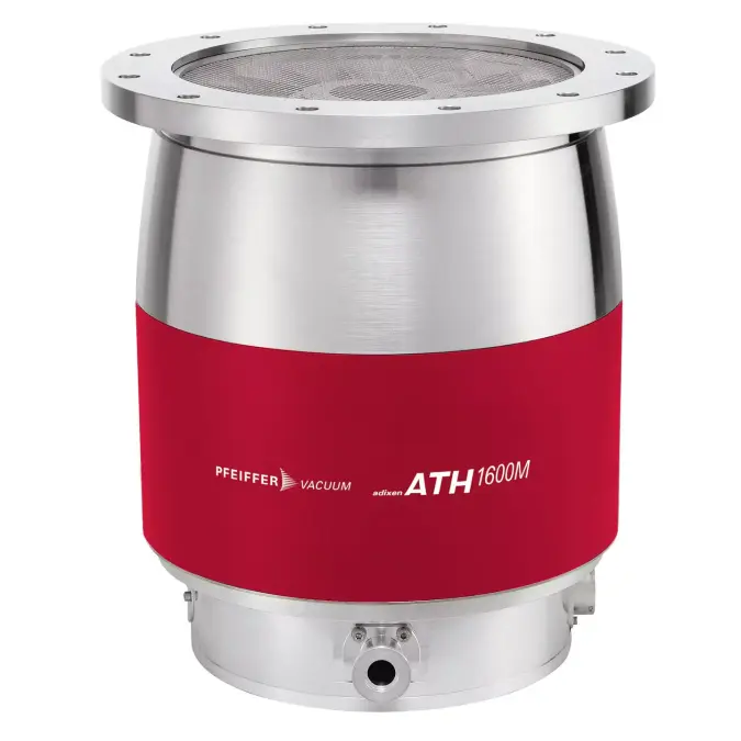
  • ATH M and MT: Turbo drag pumps with Holweck stages, sealing gas system and heating for corrosive gas applications

4.9.3.3 Drives and accessories

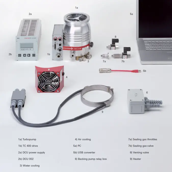
A variety of controls, displays and drives are available for operating turbopumps in different applications as well as extensive accessories. The numbering used below is based upon Figure 4.31.
Turbopumps (1a) are generally equipped with an attached drive (1b). The DC power supply comes, for example, from a plug-in power supply module (2a) with a display control unit (2b). Built-in power supply units are also available. A USB converter (5b) can also be used to connect a PC (5a) to the RS-485 interface in order to execute programming and switching functions or to transfer status displays. Profibus DP and DeviceNet converters allow the pumps to be linked to system controllers. The major switching functions can also be executed via a remote control plug using external signals. Moreover, some status displays can be taken from relay outputs.
In addition to the operating devices, various accessories are also available for special applications.
Some DCU power supply units enable a vacuum gauge to be connected in order to show the pressure as well as information on the turbopump.
With the aid of the backing pump relay box (6) the DCU power supply (2a) can be converted to a pumping station controller that can switch on both turbopump (1a) and backing pump simultaneously.
Either a fan (4), or water cooling (3) for high gas loads, can be attached to cool the pumps.
An electric vent valve (8) vents the turbopumps if the RPM declines below a given speed. In the event of a brief power failure, the vent valve will remain closed to maintain the vacuum. The pumping station will then re-start immediately when mains voltage is restored. However this necessitates a backing pump with a safety valve that will close automatically in the event of a power failure.
For UHV applications, a heater (9) can be connected to the pump that switches on automatically after a preselected rotation speed is attained, and switches off when the rpm decreases.
Electromagnetic sealing gas valves (7b) with matching throughputs, as well as sealing gas throttles (7a) for pumps of various sizes, are available for corrosive gas pumps.