Challenges in achieving ultra-high vacuum
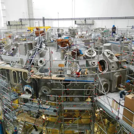
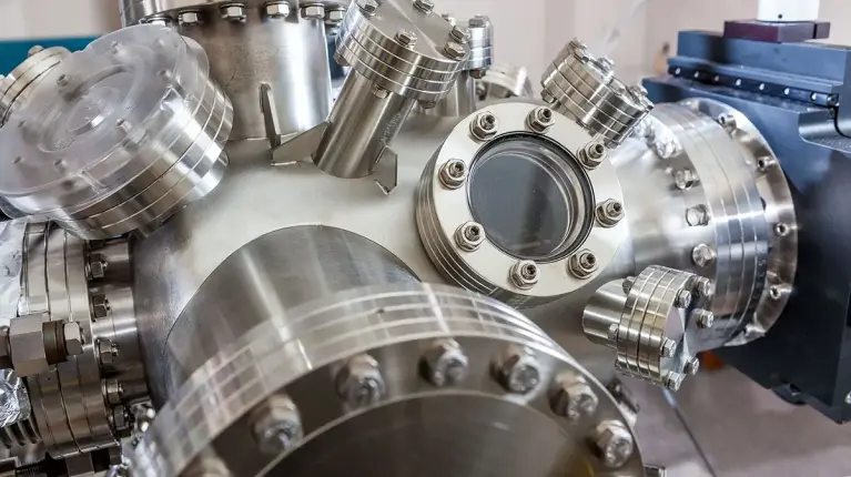
To generate ultra-high vacuum (UHV) – typically defined as pressures below 10⁻⁷ hPa (mbar) – a coordinated and precise system design is essential. Even the smallest sources of contamination can have a major impact: A single fingerprint left inside a chamber can lead to hours of additional pump-down time. This level of sensitivity highlights just how clean, controlled, and well-planned a UHV system must be from the very beginning.Key questions to consider during planning include:
- Material selection: How does material selection impact the achievable vacuum level and long-term stability?
- Chamber design: What role do vacuum chamber design and surface treatment play in minimizing gas load and avoiding trapped volumes?
- Leak rate management: How can potential leaks be identified and eliminated during system assembly?
- Pump configuration: What pump technology and compression ratios are required to reliably reach UHV conditions?
Find all the answers and further information in the FAQ.