7.2.1 Design of a leak detector with a mass spectrometer
The operating principle of quadrupole mass spectrometers is shown in chapter 6.3. These units are used both purely as residual gas analyzers or process gas analyzers as well as for leak detection. Inlet systems for analyzing gas mixtures at higher pressures, including for leak detection, are described in chapter 6.3.5. Gas analysis systems on the basis of quadrupole mass spectrometers can be used as multi-gas leak detectors.The operating principle of sector mass spectrometers is shown in chapter 6.2.
The spectrometer cell of a leak detector shown in Figure 7.2 also only works at pressures under 10-4 hPa. In leak detectors, this pressure is generated and maintained by the pumping system of the leak detector. This does not require any operator intervention.
-
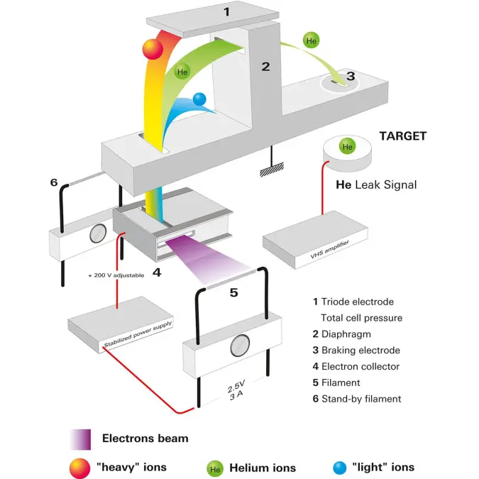
Figure 7.2: Working principle of a sector mass spectrometer

Leak detectors with mass spectrometric analyzers are designed as shown in the diagram in Figure 7.3.
-
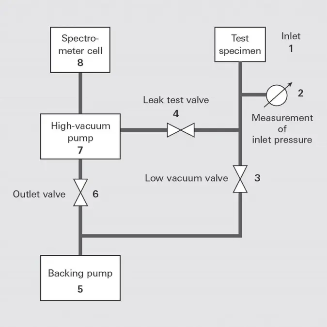
Figure 7.3: General leak detector flow chart

A mass spectrometer (spectrometer cell (8)) for masses 2, 3 and 4 (corresponding to test gases H2, 3He and 4He) is attached to the inlet flange of a turbopump (high vacuum pump (7)). A backing pump evacuates the turbopump through the exhaust valve (6). A test specimen (in DIN EN 1330-8 also referred to as “test object”) is evacuated through the inlet with the valve (3) open. Valves (6) and (3) are connected in such a manner that the required backing vacuum pressure of the turbopump always takes priority over evacuation of the test specimen. Once the test specimen has been evacuated, it can be connected to the backing vacuum or to the interstage pump of the turbopump via valve (4), depending on the pressure range concerned. Test gas is now sprayed onto the test specimen from the outside and together with the ambient air penetrates into the test specimen through leaks. The test gas present in the residual gas flows counter to the pumping direction through the turbopump via valves (3) and (6) to the spectrometer cell, where it is detected. The different compression ratios of the turbopump for air and the light test gas helium, which differ by multiple powers of ten, are utilized for this purpose.
While the high compression ratio of the turbopump keeps air away from the mass spectrometer, light gases arrive there at a relatively high partial pressure. The turbopump thus acts as a selective filter for helium and hydrogen. This is why a mass spectrometer enables helium and hydrogen to be detected in the test specimen even at pressures < 10 hPa (higher for some devices). Several powers of ten of the helium partial pressure, and thus a leakage rate range in the counterflow of between 1 and 10-9 Pa m3 s-1 can be covered by means of various interstage pumps in the high vacuum pump (4), as well as by operating it at different speeds that exponentially influence the compression ratio. A pressure in the range of several powers of 10-2 hPa must be attained in the test specimen and leak detector in the main flow for the highest sensitivity stage of the leak detector (intake via valve (4)).
Due to the upstream turbopump, the mass spectrometer always operates at an extremely low total pressure, and is thus well protected against contamination and failure.
7.2.2 Design of a leak detector with a quartz window detector
While mass spectrometric detectors separate a gas mix by ionization followed by separation in a magnetic or electrical field, quartz window detectors make use of the different permeation properties of gases.The tracer gas mix is conveyed to the quartz surface of a heated diaphragm. The carrier layer for the quartz diaphragm consists of a silicon wafer with several thousand holes through which all incoming gas atoms and molecules can reach the quartz diaphragm. The separation itself takes place at the quartz diaphragm which allows helium, but not other gases, to pass through it. The thickness and temperature of the diaphragm are influencing factors for the permeation of the helium test gas. After the gases have passed through the diaphragm, the tracer gas that has entered is ionized and the ion current is a measure of the leak rate.
-
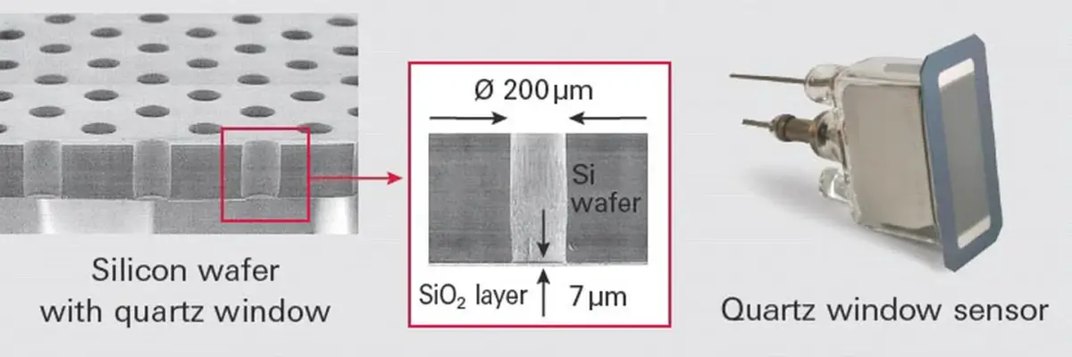
Figure 7.4: Operating principle of quartz window sensor

The unit is connected to the system to be tested (6) with a vacuum connection flange (1). The connection (3) can optionally be connected to an additional vacuum pump. To prepare the leak test, this pump can evacuate the vacuum system of the unit while the shut-off valve (9) is still closed.
The shut-off valve (9) is opened for the test. The optional pump can generate a gas flow which reduces the response time of the sensor at higher system pressures.
The sensor (2) measures the partial pressure of helium in the vacuum. A test leak (7) on the system is used to determine the response time and calibrate the unit.
To protect the sensor and to purge the unit after a strong signal, automatic purging can be carried out. The valve (4) opens the inlet with the throttle (5) and the sensor is purged briefly with atmospheric air.
-
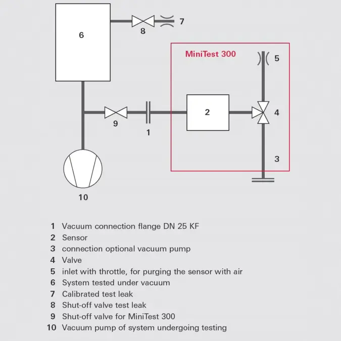
Figure 7.5: Vacuum diagram of the MiniTest quartz window leak detector on a system

-
Figure 7.5: Vacuum diagram of the MiniTest quartz window leak detector on a system
7.2.3 Test methods
The test procedure used to detect leaks depends upon the type of test specimen and the required test results. The following criteria are formulated in the standard DIN EN 1779 [34]:- Will the test specimen be tested at overpressure or in a vacuum? In selecting the test method, if possible a method should be chosen that takes into account the pressure gradient encountered when the test specimen is actually used.
- Is only a partial area or the whole area of the test specimen to be tested?
- Should local leak detection, which is used to find leaks, be carried out or should integral leak detection, where the leakage rate of test specimens is typically determined for quality assurance purposes, be performed?
Leak detectors are equipped for two operating methods:
- The vacuum method, in which the test specimen is evacuated and helium exerts its effect from the outside.
- The sniffer method, in which the workpiece is filled with test gas overpressure Δp > 100 hPa and the escaping test gas is sucked into the leak detector via a sniffer valve and detected.
7.2.4 Calibrating the leak detector
The leak detector must be calibrated in order to determine leakage rates. This is done using a commercial test leak, which generates a known and reproducible test gas rate under defined conditions. Commercial test leaks are available in the form of a permeation leak or a capillary leak with or without a test gas reservoir. Leak detectors are usually equipped with permeation leaks with a helium reservoir. For calibration, an appropriate working cycle is often built in that automatically performs the calibration.To obtain precise measurements, the unit should be calibrated before each use. To test large test specimens for which additional vacuum pumps are in use, it is advantageous to use an external test leak. The measurement accuracy can depend on where the test leak is attached. Consequently, it is necessary to take flow conditions within the vacuum area into consideration. The use of external test leaks is also useful for deter-mining the maximum response time.
7.2.5 Local leak detection
Local leak detection is used to identify leakage in a test specimen.In the vacuum method, the test specimen (vessel) is connected to the leak detector, and helium is briefly sprayed onto a suspected area using a spray gun. If the pressure in the test specimen is in the molecular flow range, i. e. < 10-3 hPa, the test speed will be dependent on the volume of the test specimen and the effective pumping speed of the test setup for helium. The smaller the test specimen or the greater the pumping speed of the leak detector or auxiliary pump used, the quicker the result is obtained. At higher pressures, particularly in the laminar flow range greater than 1 hPa, the display speed will be much slower and will be governed by the pumping speed of the leak detector‘s backing pump.
In the sniffer method according to Figure 7.6 the test specimen (3) is filled with test gas overpressure. A sniffer probe (2) is connected to the test gas connection of the leak detector. The test gas that escapes through leaks in the test specimen can be detected by sniffing with the probe.
-
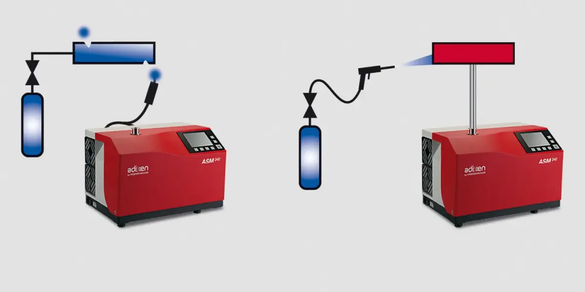
Figure 7.6: Local leak detection with sniffing and vacuum methods

Individual leaks can be identified using local leak detection. However the sum of all leakage cannot be determined. That is why this process offers only limited suitability for providing a GO / NO GO indication for quality assurance purposes.
Sniffer Leak Detection | Vacuum Leak Detection | |
|---|---|---|
Method | Sniffing the test gas-filled test object | Spraying with helium |
Mechanical strength | Against overpressure | Against atmospheric pressure from the outside against vacuum (pressure difference 1000 hPa) |
Detection limit | < 1 · 10-8 Pa m3 s-1 | < 5 · 10-13 Pa m3 s-1 |
Table 7.1: Local leak detection by sniffer and vacuum methods
7.2.6 Integral leak detection
Integral leak detection is used to determine the total leak rate, i. e. the total leak rate of all leaks in the test specimen. Here, too, the vacuum method and the sniffer method can be used.Sniffer Leak Detection | Vacuum Leak Detection | ||
|---|---|---|---|
Method | Accumulation test, collection of escaping test gas in an enclosing shell or chamber | Test specimen under overpressure, measurement of escaping test gas in a vacuum chamber | Test specimen under vacuum, measurement of test gas escaping from an enclosing shell into the test specimen |
Mechanical strength | Against overpressure of the test gas | Against overpressure of the test gas | Against atmospheric pressure from outside against vacuum (pressure differential 1000 hPa) |
Speed | slow | fast | < 5 · 10-13 Pa m3 s-1 |
Limit of detection | Use mainly > 1 · 10-5 Pa m3 s-1 | < 5 · 10-13 Pa m3 s-1 | < 5 · 10-13 Pa m3 s-1 |
Table 7.2: Integral leak detection by means of the sniffer and vacuum methods
In the integral vacuum method (method A1 in accordance with DIN EN 1779, Figure 7.7 right-hand side), the test specimen (e. g. a vacuum system) is evacuated and the surrounding space is filled with a defined quantity of test gas. The surrounding enclosure can be a plastic film or a rigid vessel. It is important that the test specimen is exposed to a defined quantity of the test gas to enable conclusions to made about the test gas concentration at the leak and a reliable quantitative conclusion to be reached.
When testing enclosed test objects (method B6 in accordance with DIN EN 1779, Figure 7.7 left-hand side) the test specimen is filled with helium and placed in an encasing vacuum vessel. The escaping test gas is identified and quantified by the leak detector.
When testing enclosed test objects (method B6 in accordance with DIN EN 1779, Figure 7.7 left-hand side) the test specimen is filled with helium and placed in an encasing vacuum vessel. The escaping test gas is identified and quantified by the leak detector.
-
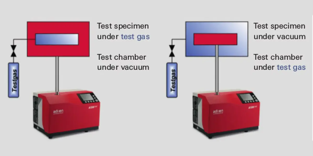
Figure 7.7: Integral leak detection with the vacuum method

In the sniffer method, the test specimen is filled with the test gas (method B3 in accordance with DIN EN 1779, Figure 7.8) and placed in an enclosing vessel. Contrary to the method described previously, this vessel does not require to be evacuated and can remain at atmospheric pressure. This means that less stringent requirements are placed on the apparatus as in the previously described method. The escaping gas is collected in the enclosing shell and needs to be mixed well during the test (using a fan, for instance) to ensure that a uniform concentration of test gas is present in the analytical chamber. The sniffer probe of the leak detector is used to determine the increase in the concentration of the test gas escaping from the test specimen which collects in the enclosing shell. The detection limit for this method is determined by the concentration of the test gas in the dead volume of the enclosing shell and the additional increase in the test gas concentration. This means that this method is considerably slower than the integral method under vacuum and its use is normally restricted to small test specimens with limited part throughput.
-
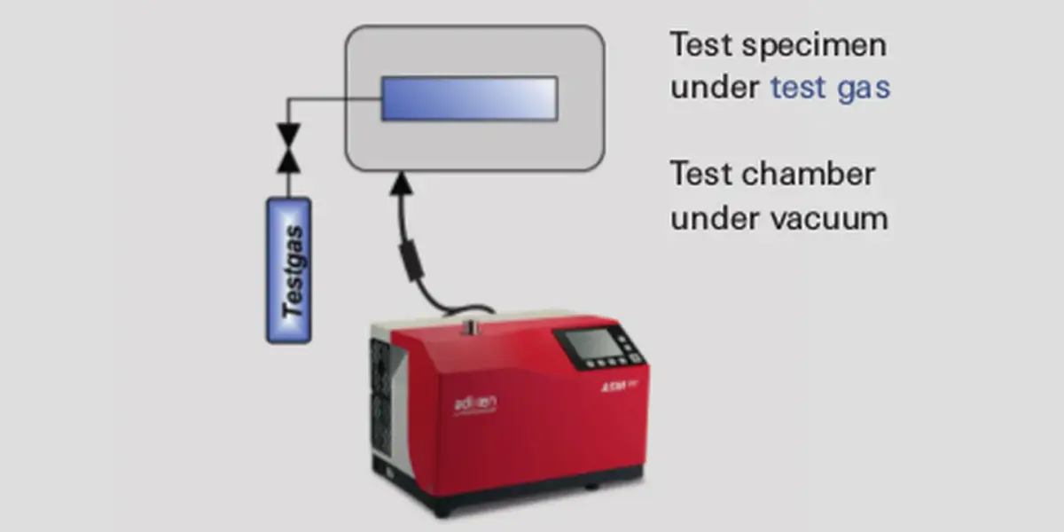
Figure 7.8: Integral leak detection of enclosed objects with the sniffer method

A fuller description of the methods and procedures for leakage testing with test gases is contained in our leak detection compendium.